


LexiconMPX G2 User Guide
1-8
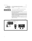
Footswitch/Footpedal
One 1/4 inch T/R/S phone jack is provided for 3 momentary footswitches.
Another 1/4 inch T/R/S phone jack is provided for a footpedal (minimum 10k to
maximum 100k impedance). Normally open or normally closed momentary
switches are suitable. At power on, the MPX G2 assumes the switch is off. Use
shielded, twisted-pair cable with shield connected to sleeve. See diagram on
previous page. See also Chapter 5: System Controls for information on pedal
calibration.
MIDI
5-pin DIN connectors are provided for MIDI THRU and OUT. A 7-pin DIN
connector is provided for MIDI IN or a powered remote. Use standard MIDI cable
assemblies, available from your local dealer.
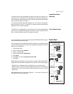
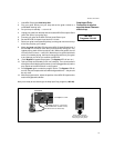
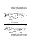
Connecting to an MPX R1
When an MPX R1 is connected to an MPX G2, two-way communication is
accomplished via MIDI System Exclusive messages. This allows immediate
response by both units to actions on either front panel.
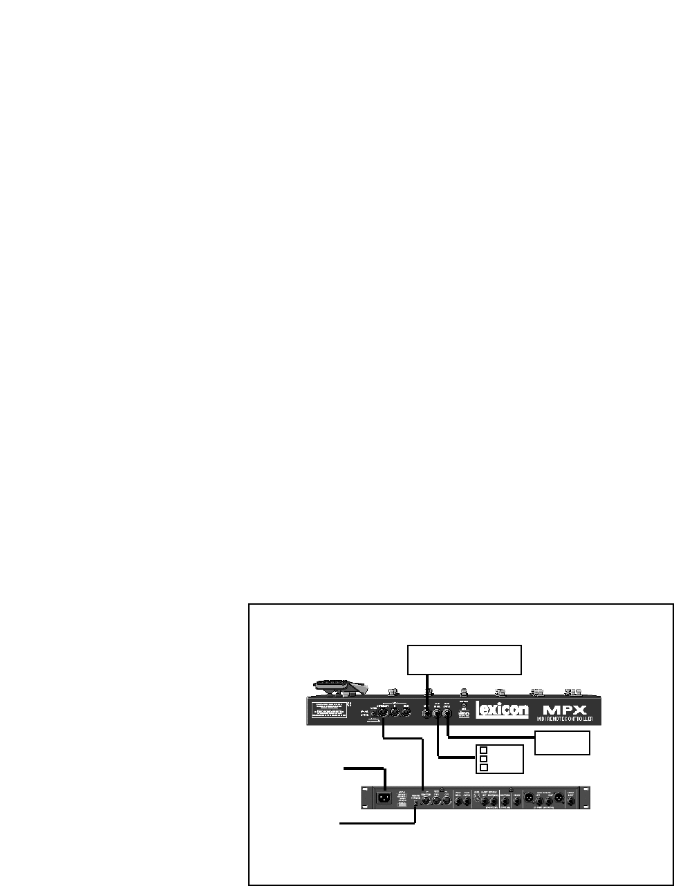
Connect the power adapter provided with the MPX R1 to the MPX G2 REMOTE
POWER input jack and to a wall outlet.
Power up the MPX G2 and connect the 7-pin DIN cable provided with the
MPX R1 between the MPX G2 rear panel IN/REMOTE jack and the MPX R1
MIDI OUT/REMOTE.
The MPX R1 will cycle through a power-up routine, lighting various LEDs, and
then display Con. The MPX G2 will display Remote Detected. These messages
indicate that proper bidirectional control has been established.
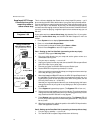
Connecting Other
Equipment
Connect a 7-pin DIN cable between the MPX (1 or G2) and the MPX R1.
Connect the MPX (1 or G2) to the MSA adapter provided with the MPX R1.
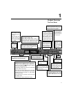
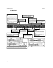
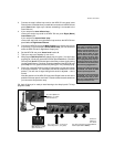
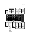
Foot
Switch
Foot Pedal
Relay
(Amp Channel Select)
to AC Power
Source
7-pin DIN
Cable
to Lexicon
MSA Adapter