


6 - 1
6. DISPLAY AND OPERATION
6. DISPLAY AND OPERATION
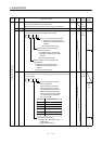
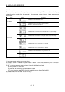
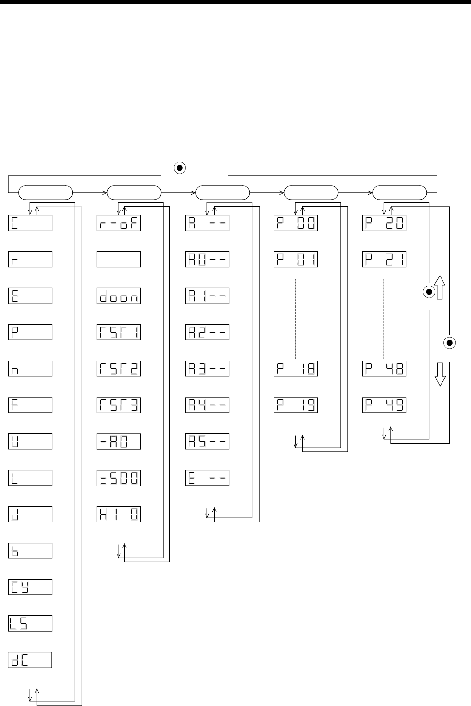
6.1 Display Flowchart
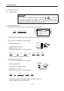
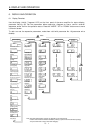
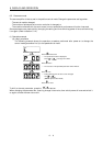
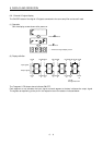
Use the display (4-digit, 7-segment LED) on the front panel of the servo amplifier for status display,
parameter setting, etc. Set the parameters before operation, diagnose an alarm, confirm external
sequences, and/or confirm the operation status. Press the "MODE" "UP" or "DOWN" button once to move
to the next screen.
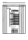
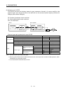
To refer to or set the expansion parameters, make them valid with parameter No. 19 (parameter write
disable).
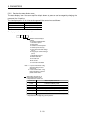
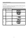
Status display
Cumulative feedback
pulses [pulse]
Motor speed
[r/min]
Droop pulses
[pulse]
Cumulative command
pulses [pulse]
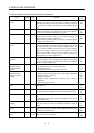
Command pulse
frequency [kpps]
Speed command voltage
Speed limit voltage[mV]
Torque limit voltage
Torque command voltage
[mV]
Regenerative load
ratio [%]
Effective load ratio
[%]
Peak load ratio
[%]
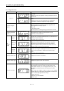
Within one-revolution
position [pulse]
Multi-revolution
counter [rev]
Load inertia moment
ratio [times]
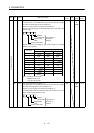
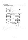
Diagnosis
Sequence
External I/O
signal display
Output signal
forced output
Test operation
Jog feed
Test operation
Positioning operation
Test operation
Motor-less operation
Software
version L
Software
version H
Automatic VC
offset
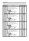
Current alarm
Last alarm
Second alarm
in past
Third alarm
in past
Fourth alarm
in past
Fifth alarm
in past
Sixth alarm
in past
Parameter
error No.
Basic parameters
Parameter No. 0
Parameter No. 1
Parameter No. 18
Parameter No. 19
Expansion
parameters
Parameter No. 20
Parameter No. 21
Parameter No. 48
Parameter No. 49
MODE
UP
DOWN
Alarm
(Note)
(Note)
(Note)
button
Note: The initial status display at power-on depends on the control mode.
Positon control mode: Cumulative feedback pulses(C), Speed control mode: Motor speed(r),
Torque control mode: Torque command voltage(U)