


3 - 35
3. SIGNALS AND WIRING
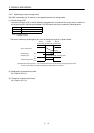
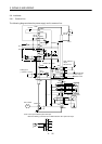
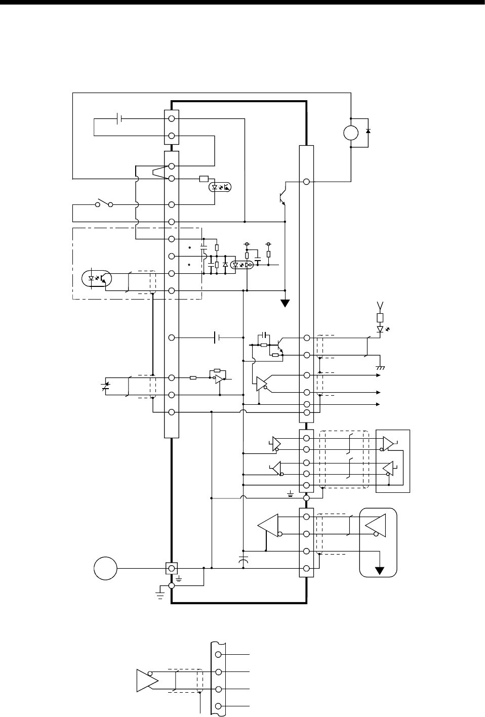
3.6 Interfaces
3.6.1 Common line
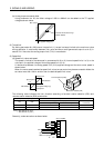
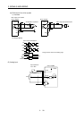
The following diagram shows the power supply and its common line.
DC24V
CNP1
P24G
P24L
CN1A
CN1B
CN1A
CN1B
DO-1
SG
OPC
SG
P15R
LG
TLA
VC etc.
SD
OP
LG
MR
MRR
SD
RA
SM
DI-1
CNP2
COM
VDD
ALM etc.
LG
ECNP2
SD
RDP
RDN
SDP
SDN
P24C
CNP1
SG
OPC
PGxNG
PP
x
NP
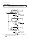
Note: For the open collector pulse train input.
Make the following connection for the differential line driver pulse train input:
Earth
Servo motor
Servo motor encoder
LA etc.
LAR etc.
Open collector
output
35mA or less
Differential line
driver output
35mA or less
SON etc.
Analog input
(
+
10V/max. current)
15VDC
±
10% 30mA
(Note)
PG NG
PP NP