


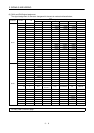
3 - 12
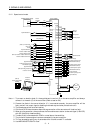
3. SIGNALS AND WIRING
Control
Mode
Signal Symbol
Connec-
tor Pin
No.
Functions/Applications
I/O
Division
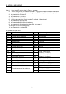
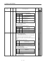
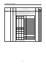
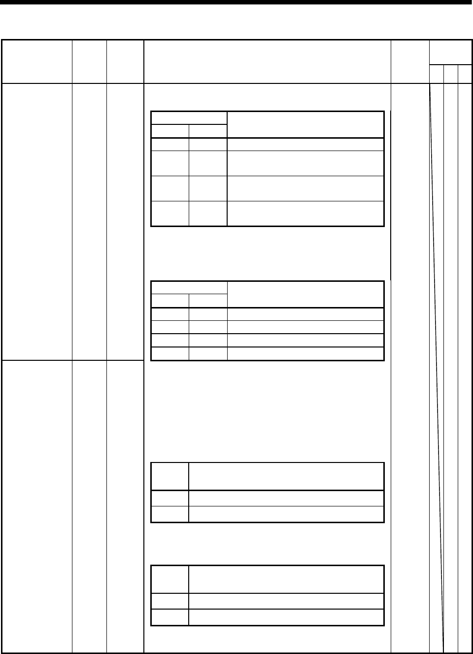
PST
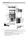
<Speed control mode>
Used to select the command speed for operation.
(Note) Input signals
SP2 SP1
Speed Command
0 0 Analog speed command (VC)
01
Internal speed command 1
(parameter No. 8)
10
Internal speed command 2
(parameter No. 9)
11
Internal speed command 3
(parameter No. 10)
Note.0:OFF (SP1/SP2-SG open)
1:ON (SP1/SP2-SG shorted)
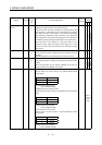
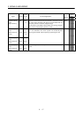
<Torque control mode>
Used to select the limit speed for operation.
(Note) Input signals
SP2 SP1
Speed Limit
0 0 Analog speed limit (VLA)
0 1 Internal speed limit 1 (parameter No. 8)
1 0 Internal speed limit 2 (parameter No. 9)
Speed selection 1 SP1 CN1A
8
1 1 Internal speed limit 3 (parameter No. 10)
Note.0:OFF (SP1/SP2-SG open)
1:ON (SP1/SP2-SG shorted)
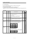
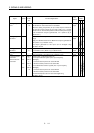
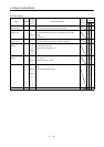
<Position/speed, speed/torque, torque/position control change mode>
As CN1B-7 acts as a control change signal, the speed
selected when the speed or torque control mode is selected is as
follows:
x When speed control mode is selected
(Note)
SP1
Speed Command
0
Analog speed command (VC)
1
Internal speed command 1 (parameter No. 8)
Note.0: OFF (SP1-SG open)
1: ON (SP1-SG shorted)
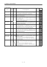
x When torque control mode is selected
(Note)
SP1
Speed Limit
0
Analog speed limit (VLA)
1
Internal speed limit 1 (parameter No. 8)
Speed selection 2 SP2 CN1B
7
Note.0: OFF (SP1-SG open)
1: ON (SP1-SG shorted)
DI-1
{{