


3 - 16
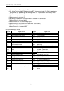
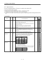
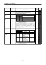
3. SIGNALS AND WIRING
Control
Mode
Signal Symbol
Connec-
tor Pin
No.
Functions/Applications
I/O
Division
PST
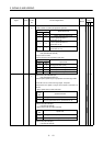
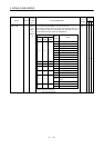
To use this signal, set 1 in parameter No. 49.
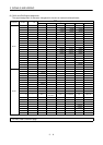
This signal is output when an alarm occurs. When there is no
alarm, respective ordinary signals (RD, INP, SA, ZSP) are output.
Alarm codes and alarm names are listed below:
(Note) Alarm Code
CN1B
19 Pin
CN1A
18 Pin
CN1A
19 Pin
Alarm
Display
Name
8888 Watchdog
A. 11 Board error 1
A. 12 Memory error 1
A. 13 Clock error
A. 15 Memory error 2
A. 17 Board error 2
A. 18 Board error 3
A. 37 Parameter error
000
A. 8E RS-232C error
0 0 1 A. 33 Overvoltage
010A. 10Undervoltage
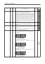
A. 50 Overload 1
011
A. 51 Overload 2
A. 24 Motor output ground fault
100
A. 32 Overcurrent
A. 31 Overspeed
A. 35
Command pulse frequency
alarm
101
A. 52 Error excessive
A. 16 Encoder error 1
110
A. 20 Encoder error 2
Alarm code CN1A
19
CN1A
18
CN1B
19
Note.0: OFF (Pin-SG open)
1: ON (Pin-SG shorted)
DO−1
∆∆∆