


3 - 10
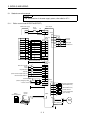
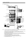
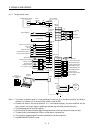
3. SIGNALS AND WIRING
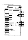
3.3.2 Signal explanations
For the I/O interfaces (symbols in I/O column in the table), refer to Section 3.6.2.
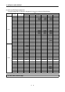
In the Control Mode field of the table
P : Position control mode, S: Speed control mode, T: Torque control mode
{: Denotes that the signal may be used in the initial setting status.
∆
: Denotes that the signal may be used by setting the corresponding parameter among parameters 43 to
49.
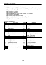
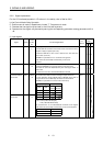
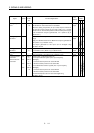
(1) Input signals
Control
Mode
Signal Symbol
Connec-
tor Pin
No.
Functions/Applications
I/O
Division
PST
Servo-on SON CN1B
5
Ready signal input terminal.
Connect SON-SG to switch on the base circuit and make the servo
amplifier ready to operate (servo on).
Disconnect SON-SG to shut off the base circuit and coast the
servo motor (servo off) .
Set1 in parameter No. 41 to switch this signal on
(keep terminals connected) automatically in the servo
amplifier.
DI-1
{{{
Reset RES CN1B
14
Alarm reset signal input terminal.
Disconnect RES-SG for more than 50ms to reset the alarm.
Some alarms cannot be deactivated by the reset signal. Refer to
Section 9.2.
The base circuit is shut off while RES-SG are shorted.
DI-1
{{{
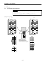
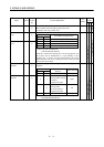
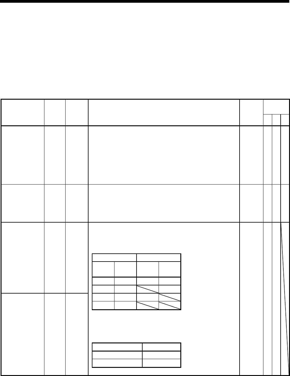
Forward/reverse rotation stroke end signal input terminals.
To start operation, short LSP-SG and/or LSN-SG. Open them to
bring the motor to a sudden stop and make it servo-locked.
Set1 in parameter No. 22 to make a slow stop.
(Note) Input signals Operation
LSP LSN
CCW
direction
CW
direction
11{{
Forward rotation
stroke end
LSP CN1B
16
01 {
10{
00
Note. 0: OFF (LSP/LSN-SG open)
1: ON (LSP/LSN-SG shorted)
Set parameter No. 41 as indicated below to switch on the signals
(keep terminals connected) automatically in the servo amplifier:
Parameter No.41 Automatic ON
1 LSP
1 LSN
Reverse rotation
stroke end
LSN CN1B
17
DI-1
{{