


3 - 9
3. SIGNALS AND WIRING
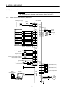
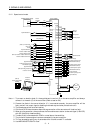
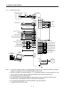
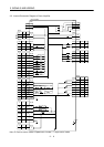
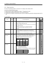
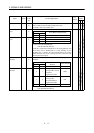
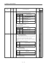
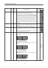
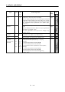
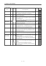
Note:1. I : Input signal, O: Output signal, -: Others (e. g. power)
2. P : Position control mode, S: Speed control mode, T: Torque control mode, P/S: Position/speed control
change mode, S/T: Speed/torque control change mode, T/P: Torque/position control change mode
3. Set parameter No. 45 to use CR.
4. Set parameter No. 47 to use PC.
5. Set parameter No. 48 to use TL.
6. By setting parameters No. 43 to 48 to make TL available, TLA can be used.
7. Set parameter No. 49 to use WNG.
8. Set parameters No. 43 to 48 to change signals.
9. Set parameter No. 49 to select alarm codes. (Refer to Chapter 9.)
10.The signal of CN1A-18 is always output.
11.Set parameter No. 1 to select MBR.
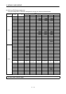
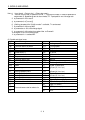
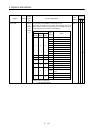
(3) Symbols and signal names
Symbol Signal Name Symbol Signal Name
SON Servo on TLC Limiting torque
LSP Forward rotation stroke end VLC Limiting speed
LSN Reverse rotation stroke end RD Ready
CR Clear ZSP Zero speed
SP1 Speed selection 1 INP In position
SP2 Speed selection 2 SA Speed reached
PC Proportion control ALM Trouble
ST1 Forward rotation start WNG Warning
ST2 Reverse rotation start OP Encoder Z-phase pulse (open collector)
TL Torque limit selection MBR Electromagnetic brake interlock
RES Reset LZ
EMG Forced stop LZR
Encoder Z-phase pulse
(differential line driver)
LOP Control change LA
VC Analog speed command LAR
Encoder A-phase pulse
(differential line driver)
VLA Analog speed limit LB
TLA Analog torque limit LBR
Encoder B-phase pulse
(differential line driver)
TC Analog torque command VDD I/F internal power supply
RS1 Forward rotation selection COM Digital I/F power supply input
RS2 Reverse rotation selection OPC Open collector power input
PP SG Digital I/F common
NP P15R DC15V power supply
PG LG Control common
NG
Forward/reverse rotation pulse train
SD Shield