


3 - 11
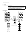
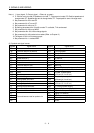
3. SIGNALS AND WIRING
Control
Mode
Signal Symbol
Connec-
tor Pin
No.
Functions/Applications
I/O
Division
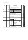
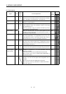
PST
Torque limit TL CN1B
9
Torque limit selection input device.
Short TL-SG to make the analog torque limit valid.
For details, refer to (2), section 3.4.1.
DI-1
{ ∆
Used to start the servo motor in any of the following directions:
(Note) Input signals
ST2 ST1
Servo Motor Starting Direction
Forward rotation
start
ST1 CN1B
8
0 0 Stop (servo lock)
0 1 CCW
10 CW
1 1 Stop (servo lock)
Reverse rotation
start
ST2 CN1B
9
Note.0: OFF (ST1/ST2-SG open)
1: ON (ST1/ST2-SG shorted)
If both ST1 and ST2 are switched on or off during operation, the
servo motor will be decelerated to a stop according to the
parameter No. 12 setting and servo-locked. When the analog
speed command (VC) is 0V, starting the servo motor will not
generate servo lock torque.
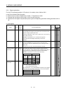
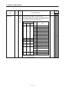
DI-1
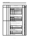
{
Used to select any of the following servo motor torque generation
directions:
(Note) Input signals
RS2 RS1
Torque Generation
Direction
Rotation Direction
Forward rotation
selection
RS1 CN1B
9
00 No torque Stop
01
Forward rotation in
driving mode / reverse
rotation in
regenerative mode
CCW
10
Reverse rotation in
driving mode /
forward rotation in
regenerative mode
CW
11 No torque Stop
Reverse rotation
selection
RS2 CN1B
8
Note.0: OFF (RS1/RS2-SG open)
1: ON (RS1/RS2-SG shorted)
DI-1
{