


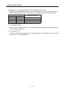
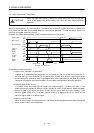
3 - 36
3. SIGNALS AND WIRING
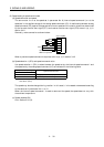
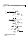
3.6.2 Detailed description of the interfaces
This section gives the details of the I/O signal interfaces (refer to I/O Division in the table) indicated in
Section 3.3.2.
Refer to this section and connect the interfaces with the external equipment.
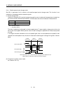
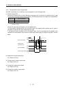
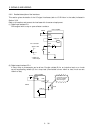
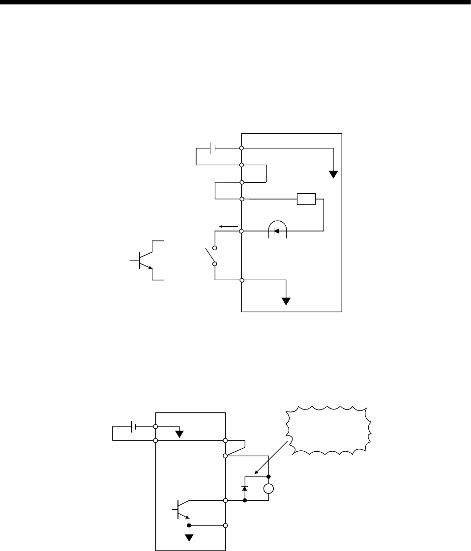
(1) Digital input interface DI-1
Give a signal with a relay or open collector transistor.
Servo amplifier
VDD
R:Approx. 4.7k
Ω
SON
etc.
Switch
SG
24VDC
For a transistor
Approx. 5mA
TR
COM
P24L
P24G
VCES
≤
1.0V
I
CEO
≤
100
µ
A
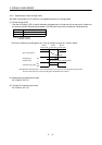
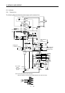
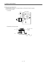
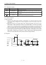
(2) Digital output interface DO-1
A lamp, relay or photocoupler can be driven. Provide a diode (D) for an inductive load, or an inrush
current suppressing resister (R) for a lamp load. (Permissible current: 40mA or less, inrush current:
100mA or less)
Servo amplifier
P24L
Load
SG
24VDC
P24G
COM
VDD
24VDC
ALM,etc.
If the diode is not
connected as shown,
the servo amplifier
will be damaged.