3 - 2
3. SIGNALS AND WIRING
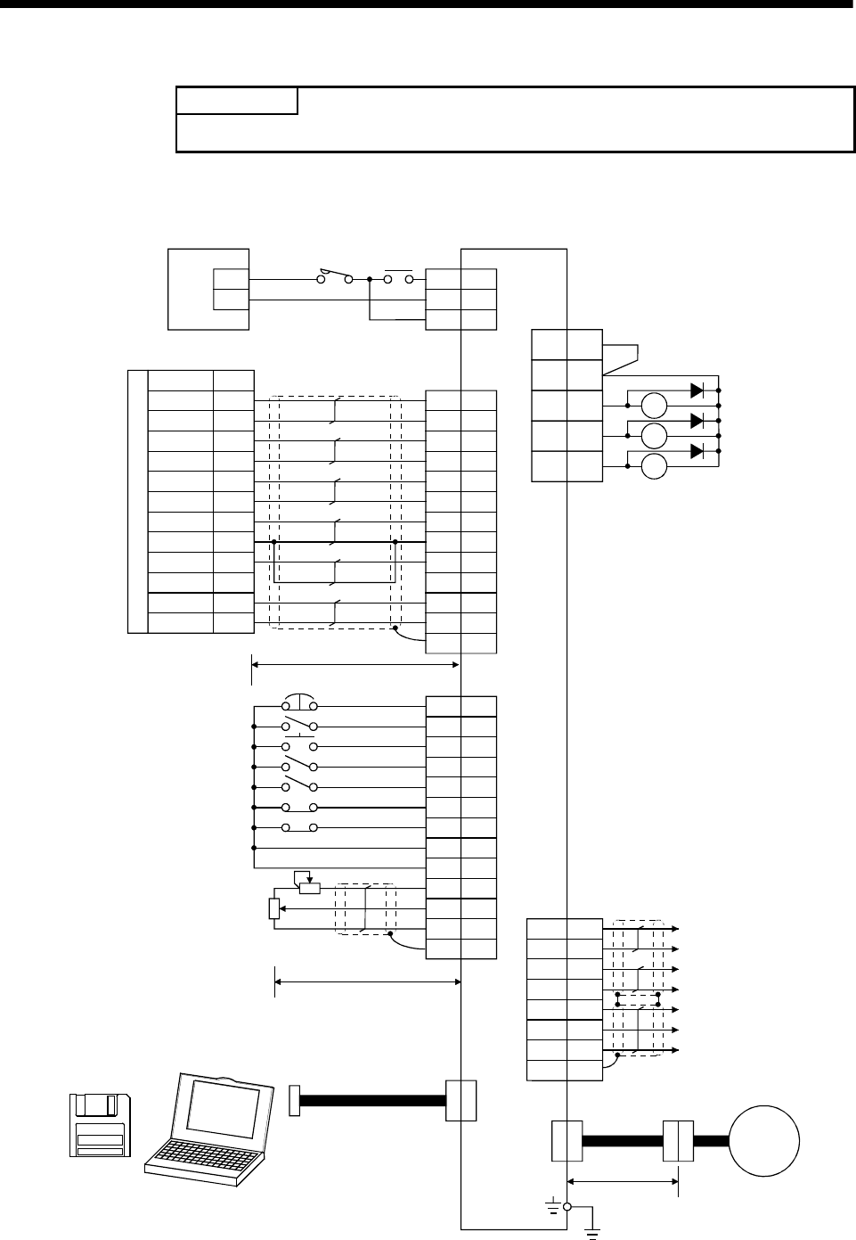
3.1 Standard connection example
POINT
y For the connection of the power supply system, refer to Section 3.7.1.
3.1.1 Position control mode AD75P (A1SD75P)
2m (6.5ft) max.
10m (32ft) max.
RA1
RA2
RA3
Personal
computer
Pin No.
21
4
22
5
23
7
26
8
25
24
18
13
2
12
8
10
19
Plate
18
15
5
PP
PG
NP
NG
CR
SG
RD
SD
INP
LZR
LZ
1
2
3
P24M
P24G
P24L
+
−
CN1A
15
5
14
8
9
16
17
Plate
20
1
11
EMG
SON
RES
PC
TL
LSP
LSN
SD
SG
P15R
SG
LG
10
12
ALM
19 ZSP
6TLC
14
7
16
17
4
LA
LAR
LB
LBR
LG
OP
P15R
SD
1
6
Plate
CNP1
Servo amplifier
CN1B
(Note 8)
(Note1)
CNP2
CNP3
+
PULSE F
+
PULSE R+
CLEAR
CLEAR COM
READY
COM
INPS
PG0 COM
PG0(+5V)
3
Positioning unit AD75P/A1SD75P
3
13 COM
3VDD
COM 9
TLA
(Note 9)
CN1A
RA
Circuit
protector
(Note 4)
CN1B
(Note 4,7)
(Note 2)
Zero speed
Limiting torque
(Note 6)
Trouble
(Note 4,7)
(Note 4,7)
30m (98ft) max.
Servo
motor
Forward rotation stroke end
Forced stop
Servo on
Reset
Proportion control
Torque limit
Reverse rotation stroke end
(Note 3)
(Note 5)
(Note 8) Analog torque limit
±10V/max. current
Encoder A-phase pulse
(differential line driver)
Encoder B-phase pulse
(differential line driver)
Control common
Encoder Z-phase pulse
(open collector)
24VDC power supply
Signal Name
Servo Configuration
software
PULSE F
−
PULSE R
−
Upper limit setting


