


3 - 3
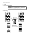
3. SIGNALS AND WIRING
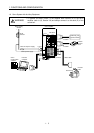
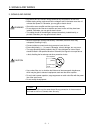
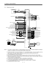
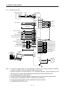
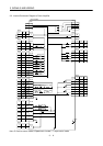
Note: 1. To prevent an electric shock, fit the supplied earth terminal (E) to the servo amplifier and always
connect it to the earth (E) of the control box. (Refer to section 3.9.)
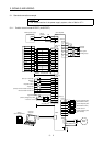
2. Connect the diode in the correct direction. If it is connected reversely, the servo amplifier will be
faulty and will not output signals, disabling the forced stop and other protective circuits.
3. The forced stop switch must be installed.
4. CN1A and CN1B have the same shape. Wrong connection of the connectors will lead to a fault.
5. When starting operation, always connect the forward/reverse rotation stroke end signal (LSN/LSP)
with SG. (Normally closed contacts)
6. Trouble (ALM) is connected with COM in normal alarm-free condition.
7. The pins with the same signal name are connected in the servo amplifier.
8. For the command pulse train input of the differential line driver system. 2m max. for the open
collector system.
9. Use MRZJW3-SETUP61E or later.