


GS2 Display—StarFire iTC
OUO6050,000223C –19–14NOV06–2/2
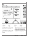
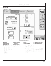
NOTE: TOGGLE button allows operator to change the
way latitude and longitude are displayed from
degrees/minutes/seconds to decimal degrees.
• Altitude: displays height of receiver, measured from
top of dome, in feet (meters) above sea level.
• GPS course: Displays direction of travel, in degrees
relative to true north (zero degrees) as measured by
receiver. Angle is measured in clockwise direction
NOTE: Course and speed normally show small
speeds and various courses even when
machine is not moving.
• GPS speed: displays ground speed of machine in
miles per hour (kilometer per hour) as measured by
receiver.
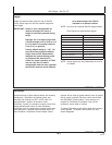
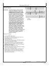
• GPS Accuracy Indicator (GPS AI): GPS AI gives
indication of GPS position accuracy achieved by
receiver, and is displayed as a percentage (0-100%)
When receiver is initially powered, GPS AI will display
0%. As receiver acquires satellites and calculates a
position, GPS AI will increase as accuracy improves.
Acceptable guidance performance for Parallel Tracking
and AutoTrac is achieved when GPS AI displays 80%
or greater. This may take up to 20 minutes. GPS
accuracy is affected by many factors. If 80% accuracy
or greater is not achieved within 25 minutes, consider
the following possibilities:
• Unobstructed view of sky – trees, buildings, or other
structures may block receiver from receiver signals
from all available satellites.
• L1/L2 signal to noise ratio (SNR) – radio interference
from 2-way radios or other sources may cause low
SNR (check satellite button – Graph)
• Satellite position in sky – poor GPS satellite
geometry can reduce accuracy (check satellite
button – SkyPlot)
• Number of satellites above elevation mask – this is
the total number of GPS satellites available to
receiver that are above 7 degrees elevation mask
(check satellite button – SkyPlot).
• Number of satellites in solution – this is total number
of satellites that are being used by receiver to
calculate a position (check satellite button– SkyPlot).
• GPS Signal Quality: Displays quality of signals being
received from constellation of GPS satellites.
• Differential Signal Quality: Displays quality of
differential correction signal being received by
receiver.
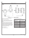
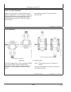
• TCM (Terrain Compensation Module):
– Roll Angle: Is both a graphical and numerical
representation of amount of roll TCM is
measuring, relative to calibrated zero degree
reference. A positive roll angle means vehicle is
rolled to right (depicts what horizon would look
like from cab).
– Yaw Rate: This gives a graphic representation
and a numeric figure for amount of rotation TCM
is measuring. Positive yaw rate means vehicle is
turning to right.
15-3
121907
PN=11