


92
Speaker/Output Setup
—Continued
Zone 2 Out, Zone 3 Out
This item is displayed when “Zone 2 Out” or “Zone 3
Out” is specified for Analog 1-5 above. The default
setting for “Zone 2 Out” is “Pre Out (variable)” and for
“Zone 3 Out” is “Line Out (fixed).”
Pre Out (variable):
Select this when you want to set
“variable” for output to a device connected to Zone 2 or
Zone 3. You should operate the DTR-10.5 to adjust the
sound volume from the device in Zone 2 or Zone 3.
Line Out (fixed):
Select this when you want to set
“fixed” for output to a device connected to Zone 2 or
Zone 3. You should operate the amplifier connected to
the terminal to adjust the sound volume from the device
in Zone 2 or Zone 3.
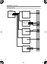
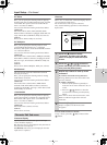
Opt 1 Out, Opt 2 Out, Coax 1 Out, Coax 2 Out
Specify a setting for “DIGITAL OUT OPTICAL 1-2”
and “DIGITAL OUT COAXIAL 1-2.”
You can select from Tape 1 Rec Out, Tape 2 Rec Out,
Video 1 Rec Out, Video 2 Rec Out, Video 3 Rec Out,
Zone 2 Out, Zone 3 Out, and Not Used.
Example 1:
When input (REC) of an audio recording device (e.g.,
an MD recorder) with TAPE 2 as an input source is
connected to DIGITAL OUT OPTICAL 1, set “Opt 1
Out” to “Tape 2 Rec Out.”
Example 2:
When input (IN) of a picture recording device (e.g., a
DVD recorder) with VIDEO 2 as an input source is
connected to DIGITAL OUT OPTICAL 2, set “Opt 2
Out” to “Video 2 Rec Out.”
When nothing is connected:
Select “Not Used.”
HDMI Out
This sub-menu appears when the HDMI terminal board
[L] is inserted.
This setting allows you to enable/disable audio output
from the HDMI terminal. Use this setting when the
HDMI terminal of a TV is connected to the HDMI
terminal of the DTR-10.5 and you want to enable
HDMI audio output of the DTR-10.5 from the TV
speakers. Usually leave this setting to its default,
“Disable.”
Disable (Default):
Disables HDMI audio output.
Enable:
Enables HDMI audio output.
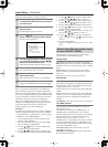
This setting allocates video output jacks on the
DTR-10.5 to input (play) sources. The setting varies
depending on the connection conditions.
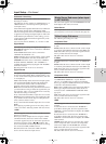
The DTR-10.5 is equipped with composite video output
jacks for four lines, and S video output jacks for four
lines.
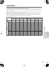
The default settings are as follows:
Composite Video 1-3, S-Video 1-3
This is a setting for the composite video output jacks
(VIDEO OUT 1-3) and S video output jacks (S VIDEO
OUT 1-3).
For Composite Video 1-3, you can select from Monitor
Out A, Monitor Out B, Video 1 Rec Out, Video 2 Rec
Out, Video 3 Rec Out, Zone 2 Out, Zone 3 Out, and Not
Used.
• You can set “Zone 2 Out” or “Zone 3 Out” only when
“Zone 2 Out” or “Zone 3 Out” is selected from the
Audio Output Assign sub-menu.
For S Video 1-3, you can select from Monitor Out A,
Monitor Out B, Video 1 Rec Out, Video 2 Rec Out,
Video 3 Rec Out, and Not Used.
Example 1:
When the video port of a picture recording device (e.g.,
a VCR) with VIDEO 1 as an input source is connected
to VIDEO OUT 2, you should set “Composite Video 2”
to “Video 1 Rec Out.”
Example 2:
When you want to connect a TV set to VIDEO OUT 3
to watch it in main room A, set “Composite Video 3” to
“Monitor Out A.”
When nothing is connected:
Select “Not Used.”
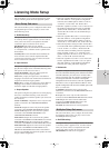
Composite Video 4, S-Video 4
The composite video output jacks (VIDEO OUT 4), and
S video output jacks (S VIDEO OUT 4) are fixed to
Monitor Out A, you cannot change this setting. You
should connect a TV set and a projector used in main
room A to VIDEO OUT 4 or S VIDEO OUT 4.
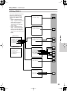
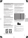
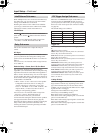
Video Output Assign Sub-menu
22
11
OUT
DIGITAL
Terminals
Default input
settings
Composite Video 1 (VIDEO OUT 1) Monitor Out B
Composite Video 2 (VIDEO OUT 2) Zone 2 Out
Composite Video 3 (VIDEO OUT 3) Zone 3 Out
Composite Video 4 (VIDEO OUT 4) Monitor Out A (fixed)
S-Video 1 (S VIDEO OUT 1) Video 1 Rec Out
S-Video 2 (S VIDEO OUT 2) Video 2 Rec Out
S-Video 3 (S VIDEO OUT 3) Video 3 Rec Out
S-Video 4 (S VIDEO OUT 4) Monitor Out A (fixed)
2
1
4
3
S VIDEOS VIDEO VIDEOVIDEO
OUT OUT