


47
Installation and Connections
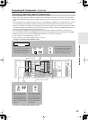
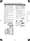
Connecting -compatible AV Components
The
terminal on the DTR-10.5 is for connecting
other Integra/Onkyo components equipped with the
same
terminal. When a component is connected to
the
terminal, it can be operated by the remote
controller supplied with the DTR-10.5. In addition,
when you connect a component to the
terminal, you
can also perform the system operations given below.
Power on/ready function
When the DTR-10.5 is in the standby state, if an
-
connected component is turned on, the DTR-10.5 also
turns on and the input source selected at the DTR-10.5
automatically switches to that component.
Be aware that this function will not work if the power cord
for the
-connected component is connected to the AC
OUTLET on the DTR-10.5, or if the DTR-10.5 has
already been turned on.
Direct change function
When the play button is pressed on an
-connected
component, the input source selected at the DTR-10.5
automatically changes to that component.
Power off function
When the DTR-10.5 is placed in the standby state, all
-connected components are also automatically put
into the standby state.
Also, if you press the [On] button on the DTR-10.5
remote controller while the DTR-10.5 is turned on, all
-connected components (DVD players, CD players,
MD recorders, tuners, etc.) are also turned on.
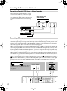
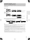
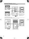
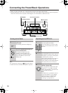
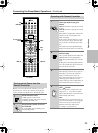
To connect components using the
terminal, simply
connect a remote control cable from this
terminal to
the
terminal of the other component. An
remote
control cable with a 1/8 inch (3.5 mm) miniature two-
conductor plug comes with every cassette tape deck,
compact disc player, MD recorder, and DVD player that
has an
terminal.
• When performing operations with
-connected
components using the
system, do not use the
remote zone (Zone 2/Zone3).
• For remote control operation, the audio connection
cables must also be connected.
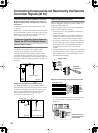
• If a component has two
terminals, you can use
either one to connect to the DTR-10.5. The other one
can be used to daisy chain with another component.
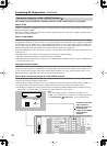
• With Integra DVD players, you can enter the pre-
program code so that you can operate the DVD player
directly with the remote controller without connecting
the
terminals (See page 129).
E
GND
RS
232
IR
IN
+
12
V DC PWR SUPPLY
MAIN
GND
ZONE
3
ZONE
2
20mA MAX.
12 V
TRIGGER
OUT
E
MODEL NO.
DTR
-
10.5
GND
C
D
E
B
A
12
V
TRIGGER
OUT
100mA MAX.
100mA MAX.
100mA MAX.
TOTAL
100mA MAX.
200mA MAX.
UDD
AC
INLET
FRONT
L
CENTERFRONT
R
SURR BACK
L
(
ASSIGNABLE
)
URR
R
SURR
L
FRONT
R
(
BTL
)
FRONT
L
(
BTL
)
(
SINGLE
)
AC 120V 60Hz
SWITCHED
120W 1A MAX.
AC
OUTLET
SPEAKERS A
SPEAKERS B
22
1
66
55
44
33
22
11
OPTICAL COAXIAL
AUDIO IN
1
3
2
1
PH
2
3
9
8
7
6
5
4
4
5
RL
LR
LR
R L
G
IN
1
IN
2
HDMI
S
VIDEO VIDEO
IN IN
IN
1
IN
2
3
2
1
Y
P
B
P
R
COMPONENT
VIDEO
IN
3
6
5
4
Y
P
B
P
R
2
1
4
3
ANTENNA
FM
75
SURR BACK
R
(
ASSIGNABLE
)
DIGITAL IN DIGITAL IN
LR
S VIDEOS VIDEO VIDEOVIDEO
CD
OUT
OUT
F
L
OUT
IH
OUT OUT
J
K
OUT
1
AM
1
SBR SBL
SR SL
SUB C
FR FL
SBR SBL
SR SL
SUB C
FR
FL
MULTI
-
CH
IN
1
MULTI
-
CH
IN
2
OUT
Y
P
B
P
R
Y
P
B
P
R
COMPONENT VIDEO
IN
(
HD/BNC
)
REMOTE
CONTROL
L
R
ANALOG
OUTPUT
AUDIO IN
R
4
L
REMOTE
CONTROL
Integra DVD player
Remote
control
cable
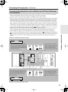
Connections for Remote Control ( )
DTR-10.5
Ex: Integra/Onkyo CD
player
connector
connector
Ex: Onkyo cassette tape
deck
Remote control cable