


36
Connecting AV Components
—Continued
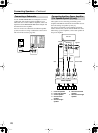
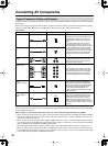
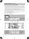
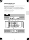
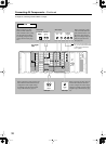
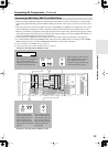
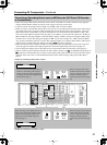
• When connecting a DVD recorder or digital VCR to the DTR-10.5, make connections for video and audio signals
using digital and analog terminals. Before making connections, refer to pages 32 and 33 for correct connections.
• This section shows the connection example when you use the VIDEO 1 as an input. In this case, you do not need
additional configurations. When connecting to other terminals within the same terminal section on the DTR-10.5,
configure the audio input assignment in the Audio Assign sub-menu (See page 94), the video input assignment in the
Video Assign sub-menu (See page 95), the audio output assignment in the Audio Output Assign sub-menu (See page
91), and the video output assignment in the Video Output Assign sub-menu (See page 92).
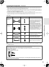
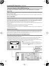
• You can change the display name for the input source to represent the actual connected device (See page 97).
• When you want to perform analog recording of the audio signal from the digital device, you have to make analog
audio signal connections. Connect the audio output terminals on the digital device to the AUDIO IN terminals on the
DTR-10.5 using analog audio cables (RCA/phono).
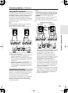
• For a model without a HDMI terminal, when you connect a DVD recorder or digital VCR to the COMPONENT ter-
minals, be sure to use the COMPONENT terminals to connect a TV or projector.
*For more information on the HDMI interface, see page 45.
*For more information on the i.LINK (AUDIO) interface, see page 42.
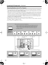
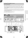
Example for connecting with the VIDEO 1 as input
Connecting a DVD Recorder or Digital VCR (VIDEO 1)
E
GND
“Net
-
Tune”
is
a
trademark
of
Onkyo
Corporation.
ETHERNET
(
Net
-
Tune
)
A
RS
232
IR
IN
+
12
V DC PWR SUPPLY
MAIN
GND
ZONE
3
ZONE
2
20mA MAX.
12 V
TRIGGER
OUT
E
GND
C
D
E
B
A
12
V
TRIGGER
OUT
100mA MAX.
100mA MAX.
100mA MAX.
TOTAL
100mA MAX.
200mA MAX.
FRONT
L
CENTERFRONT
R
SURR BACKL
(
ASSIGNABLE
)
SURR
R
SURR
L
22
1
66
55
44
33
2 2
11
OPTICAL COAXIAL
AUDIO IN
1
3
2
1
PH
2
3
9
8
7
6
5
4
4
5
RL
LR
LR
R L
G
IN
1
IN
2
HDMI
S
VIDEO VIDEO
IN IN
IN
1
IN
2
3
2
1
Y
P
B
P
R
COMPONENT
VIDEO
IN
3
6
5
4
Y
P
B
P
R
2
1
4
3
ANTENNA
FM
75
SURR BACKR
(
ASSIGNABLE
)
DIGITAL IN DIGITAL IN
LR
S VIDEOS VIDEO VIDEOVIDEO
CD
OUT
OUT
F
L
OUT
IH
OUT OUT
J
K
OUT
1
AM
1
SBR SBL
SR SL
SUB C
FR FL
SBR SBL
SR SL
SUB C
FR
FL
MULTI
-
CH
IN
1
MULTI
-
CH
IN
2
B
OUT
Y
P
B
P
R
Y
P
B
P
R
COMPONENT VIDEO
IN
(
HD/ BNC
)
Y
P
B
PR
COMPONENT
OUT (RCA)
R
L
ANALOG
S VIDEO
IN
DIGITAL
COAXIAL
AUDIO IN
AUDIO IN
R
L
ANALOG
DIGITAL
COAXIAL
AUDIO OUT
VIDEO
IN
S VIDEO
OUT
VIDEO
OUT
AUDIO OUT
Digital video recorder
(DVD recorder, digital VCR)
When connecting to other
audio terminals within same
terminal section, configure
the audio input settings
accordingly using the Audio
Assign sub-menu (See page
94).
When connecting to other
audio terminals within the
same terminal section, con-
figure the audio output set-
tings accordingly using the
Audio Output Assign sub-
menu (See page 91).
When connecting to other video
terminals within the same termi-
nal section, configure the video
input settings accordingly using
the Video Assign sub-menu (See
page 95).
When connecting to other
video terminals within the
same terminal section, con-
figure the video output set-
tings accordingly using the
Video Output Assign sub-
menu (See page 92).
Audio Output Video Output
Audio Input Video Input