


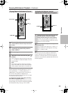

73
Operations
Enjoying Net Audio
—Continued
Notes:
• To use Internet radio with the DTR-10.5, your broad-
band Internet connection needs to be up and running
and able to access the Web. Please consult your ISP if
you have any problems with your Internet connec-
tion.
• The DTR-10.5 uses DHCP and AutoIP to configure
its network settings automatically. If you want to con-
figure these settings manually, see page 121.
• The DTR-10.5 does not support PPPoE settings, so if
you have a PPPoE-type Internet connection, you must
use a PPPoE-compatible router.
• Depending on your ISP, you may need to specify a
proxy server to use Internet radio. If your PC is con-
figured to use a proxy server, use the same settings
(see page 121).
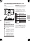
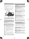
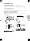
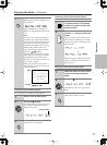
To connect the DTR-10.5 to your Ethernet network, plug one end of a CAT5 Ethernet cable into the ETHERNET (Net-
Tune) port, and plug the other end into a LAN port on your router or switch.
The following diagram shows how you can connect the DTR-10.5 to your Ethernet network. Here it’s connected to a
LAN port on the router, which has a 4-port 100Base-TX switch built-in.
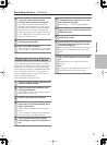
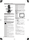
You can connect any number of DTR-10.5s to the network, and the Network Audio server can serve up to three clients
simultaneously, so you can enjoy Net-Tune in three separate rooms simultaneously. The following diagram shows a Net-
Tune network with two DTR-10.5s.
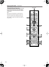
Networking Your DTR-10.5
E
GND
“Net
-
Tune”
is
a
trademark
of
Onkyo
Corporation.
ETHERNET
(
Net
-
Tune
)
A
RS
232
IR
IN
+
12
V DC PWR SUPPLY
MAIN
GND
ZONE
3
ZONE
2
20mA MAX.
12 V
TRIGGER
OUT
E
MODEL NO.
DTR
-
10.5
GND
C
D
E
B
A
12
V
TRIGGER
OUT
100mA MAX.
100mA MAX.
100mA MAX.
TOTAL
100mA MAX.
200mA MAX.
UDD
AC
INLET
A
L
R
FRONT SURR SURR
BACK
CENTER
SUB
WOOFER
SUB
WOOFER
FRONT
L
CENTERFRONT
R
SURR BACK
L
(
ASSIGNABLE
)
SURR
R
SURR
L
FRONT
R
(
BTL
)
FRONT
L
(
BTL
)
PRE
OUT
A
(
SINGLE
)
PRE
OUT B
AC 120V 60Hz
SWITCHED
120W 1A MAX.
AC
OUTLET
SPEAKERS A
SPEAKERS B
22
1
66
55
44
33
22
11
OPTICAL COAXIAL
AUDIO IN
1
3
2
1
PH
2
3
9
8
7
6
5
4
4
5
RL
LR
LR
R L
G
IN
1
IN
2
HDMI
S
VIDEO VIDEO
IN IN
IN
1
IN
2
3
2
1
Y
P
B
P
R
COMPONENT
VIDEO
IN
3
6
5
4
Y
P
B
P
R
2
1
4
3
ANTENNA
FM
75
B
SURR BACK
R
(
ASSIGNABLE
)
DIGITAL IN DIGITAL IN
LR
S VIDEOS VIDEO VIDEOVIDEO
CD
OUT
OUT
F
L
OUT
IH
OUT OUT
J
K
OUT
1
AM
1
SBR SBL
SR SL
SUB C
FR FL
SBR SBL
SR SL
SUB C
FR
FL
MULTI
-
CH
IN
1
MULTI
-
CH
IN
2
B
OUT
Y
P
B
P
R
Y
P
B
P
R
COMPONENT VIDEO
IN
(
HD/BNC
)
ETHERNET
(
Net
-
Tune
)
Network Audio server
LAN port
LAN port
WAN port
Internet radio
Modem
Router
LAN/
Ethernet
port/
DTR-10.5
Internet radio
WAN port
Router
LAN port
LAN port
LAN port
Modem
Room 1
Room 2
LAN/
Ethernet
port/
Network Audio server