


38
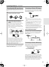
Connecting AV Components
—Continued
E
GND
“Net
-
Tune”
is
a
trademark
of
Onkyo
Corporation.
ETHERNET
(
Net
-
Tune
)
A
RS
232
IR
IN
+
12
V DC PWR SUPPLY
MAIN
GND
ZONE
3
ZONE
2
20mA MAX.
12 V
TRIGGER
OUT
E
GND
C
D
E
B
A
12
V
TRIGGER
OUT
100mA MAX.
100mA MAX.
100mA MAX.
TOTAL
100mA MAX.
200mA MAX.
FRONT
L
CENTERFRONT
R
SURR BACKL
(
ASSIGNABLE
)
SURR
R
SURR
L
22
1
66
55
4 4
33
22
11
OPTICAL COAXIAL
AUDIO IN
1
3
2
1
PH
2
3
9
8
7
6
5
4
4
5
RL
LR
LR
R L
G
IN
1
IN
2
HDMI
S
VIDEO VIDEO
IN IN
IN
1
IN
2
3
2
1
Y
P
B
P
R
COMPONENT
VIDEO
IN
3
6
5
4
Y
P
B
P
R
2
1
4
3
ANTENNA
FM
75
SURR BACKR
(
ASSIGNABLE
)
DIGITAL IN DIGITAL IN
LR
S VIDEOS VIDEO VIDEOVIDEO
CD
OUT
OUT
F
L
OUT
IH
OUT OUT
J
K
OUT
1
AM
1
SBR SBL
SR SL
SUB C
FR FL
SBR SBL
SR SL
SUB C
FR
FL
MULTI
-
CH
IN
1
MULTI
-
CH
IN
2
B
OUT
Y
P
B
P
R
Y
P
B
P
R
COMPONENT VIDEO
IN
(
HD/ BNC
)
Y
P
B
PR
COMPONENT
OUT (BNC)
R
L
ANALOG
S VIDEO
IN
AUDIO IN
R
L
ANALOG
AUDIO OUT
S VIDEO
OUT
VIDEO
OUT
AUDIO OUT
DIGITAL
OPTICAL
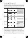
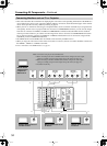
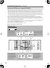
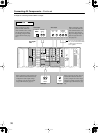
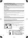
When connecting to other
audio terminals within the
same terminal section, config-
ure the audio input settings
accordingly using the Audio
Assign sub-menu (See page
94).
When connecting to other audio termi-
nals within the same terminal section,
configure the audio output settings
accordingly using the Audio Output
Assign sub-menu (See page 91).
When connecting to other
video terminals within the
same terminal section, con-
figure the video input set-
tings accordingly using the
Video Assign sub-menu
(See page 95).
When connecting to other video ter-
minals within the same terminal
section, configure the video output
settings accordingly using the Video
Output Assign sub-menu (See page
92).
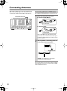
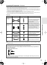
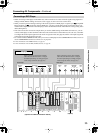
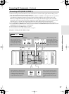
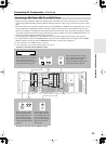
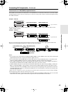
For digital
VCR
Example for connecting with the VIDEO 3 as input
VCR
* For USA and Canadian mod-
els, you can select either BNC
or RCA type board at the
user’s option.
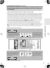
Audio Outpuit Video Output
Audio Input Video Input