


41
Installation and Connections
Connecting AV Components
—Continued
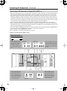
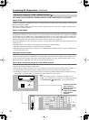
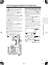
• When connecting a MD recorder, DAT deck or CD recorder to the DTR-10.5, make connections using digital or
analog terminals. Before making connections, refer to page 32 for correct connections.
• Connect a cassette or DAT tape deck to TAPE1, and an MD or CD recorder to TAPE 2.
• When you connect a cassette deck to the DTR-10.5, be sure to use only analog audio terminals. In the initial settings,
no terminal of this unit is assigned to a REC terminal of the cassette deck. To achieve the assignment, connect the
REC terminal of the cassette deck to any of the AUDIO OUT 1 to 5 terminals and set the terminal to “Tape 1 Rec
Out” in the Audio Output Assign sub-menu (See page 91). In addition, you can switch the input source “TAPE2” to
MD or CDR. Press the [Tape 2] button on the front panel to display “TAPE 2,” then press the [Tape 2] button again
and hold it for 3 seconds. This changes the display to “MD.” If you wish to change it to “CDR,” release the button
once, and press and hold it again for 3 seconds. This operation enables you to operate Onkyo’s MD or CD recorders
with the remote controller of this unit (Please note that the connection is required).
• When connecting to other terminals, remember to configure the audio input assignment in the Audio Assign sub-
menu (See page 94) and the audio output assignment in the Audio Output Assign sub-menu (See page 91).
• You can change the display name for the input source to represent the actual connected device (See page 97).
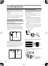
• When you want to perform analog recording of an audio signal or operate your -compatible Integra products via
connections with the DTR-10.5, you have to make analog audio signal connections. Connect the audio output
terminals on the source device to the AUDIO IN terminals on the DTR-10.5 using analog audio cables (RCA/
phono).
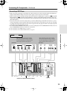
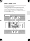
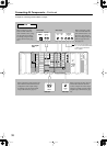
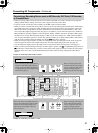
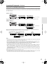
Connecting a Recording Device such as MD Recorder, DAT Deck, CD Recorder
or Cassette Deck
E
GND
“Net
-
Tune”
is
a
trademark
of
Onkyo
Corporation.
ETHERNET
(
Net
-
Tune
)
A
RS
232
IR
IN
+
12
V DC PWR SUPPLY
MAIN
GND
ZONE
3
ZONE
2
20mA MAX.
12 V
TRIGGER
OUT
E
GND
C
D
E
B
A
12
V
TRIGGER
OUT
100mA MAX.
100mA MAX.
100mA MAX.
TOTAL
100mA MAX.
200mA MAX.
FRONT
L
CENTERFRONT
R
SURR BACK
L
(
ASSIGNABLE
)
SURR
R
SURR
L
PRE
OUT
A
(
SINGLE
)
2 2
1
66
55
44
3 3
22
1 1
OPTICAL COAXIAL
AUDIO IN
1
3
2
1
PH
2
3
9
8
7
6
5
4
4
5
RL
LR
LR
R L
G
IN
1
IN
2
HDMI
S
VIDEO VIDEO
IN IN
IN
1
IN
2
3
2
1
Y
P
B
P
R
COMPONENT
VIDEO
IN
3
6
5
4
Y
P
B
P
R
2
1
4
3
ANTENNA
FM
75
SURR BACK
R
(
ASSIGNABLE
)
DIGITAL IN DIGITAL IN
LR
S VIDEOS VIDEO VIDEOVIDEO
CD
OUT
OUT
F
L
OUT
IH
OUT OUT
J
K
OUT
1
AM
1
SBR SBL
SR SL
SUB C
FR FL
SBR SBL
SR SL
SUB C
FR
FL
MULTI
-
CH
IN
1
MULTI
-
CH
IN
2
B
OUT
Y
P
B
P
R
Y
P
B
P
R
COMPONENT VIDEO
IN
(
HD/ BNC
)
R
L
R
L
ANALOG
DIGITAL
OPTICAL
AUDIO IN
AUDIO OUT
DIGITAL
OPTICAL
AUDIO OUT
ANALOG
AUDIO OUT
DIGITAL
OPTICAL
AUDIO IN
DIGITAL
COAXIAL
AUDIO OUT
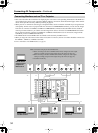
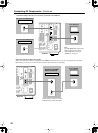
Example for connecting with the TAPE 1 as input
Example for connecting to the TAPE 2 as input
When connecting to other digital audio ter-
minals or to other analog audio output ter-
minals, configure the audio output settings
accordingly using the Audio Output Assign
sub-menu (See page 91).
When connecting to other audio
terminals within the same terminal
section, configure the audio input
settings accordingly using the
Audio Assign sub-menu (See page
94).
When connecting to other digital audio termi-
nals or to other analog audio output terminals,
configure the audio output settings accord-
ingly using the Audio Output Assign sub-
menu (See page 91).
When connecting to other audio ter-
minals within the same terminal
section, configure the audio input
settings accordingly using the
Audio Assign sub-menu (See page
94).
Cassette deck or DAT deck
MD recorder or CD recorder