


17
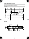
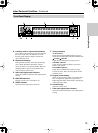
Index Parts and Facilities
—Continued
1
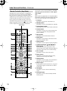
DIGITAL OPTICAL IN/OUT
The input/output terminals for digital sound signal.
The sound quality equals the signal passed through
the COAXIAL terminals.
2
DIGITAL COAXIAL IN/OUT
The input/output terminals for digital sound signal.
The sound quality equals the signal passed through
the OPTICAL terminals.
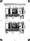
3
MULTI-CH IN 1/2 (Australian model)
This connector is for connecting components with a
multichannel output.
Two sets of multichannel input terminals are
available on the DTR-10.5.
4
AUDIO IN/OUT
These connectors are for connecting to the audio
input and output jacks on audio/video components.
To connect a turntable, connect to the PH jacks.
In addition to the PH jacks, the DTR-10.5 offers nine
input and five output jacks.
5
VIDEO/S VIDEO IN/OUT
These connectors are for connecting to the video
input and output jacks on video components.
Six input and 4 output jacks are available for each
of VIDEO and S VIDEO connection.
6
COMPONENT VIDEO IN/OUT
These connectors are for connecting to the compo-
nent video outputs/inputs of video components that
have them.
All models for USA, Canada and Australia are
equipped with three inputs and one output for the
RCA type COMPONENT connection. In addition
to these, the Australian model has one input and one
output for the BNC type COMPONENT connec-
tion.
For USA and Canadian models, you can select
either BNC or RCA type board at the user’s option.
Check the type of terminals or jacks on the device to
be connected before making connections.
7
ANTENNA (FM/AM)
These jacks are for connecting the FM indoor
antenna and the AM loop antenna that are supplied
with the DTR-10.5.
8
This jack is for connecting other Integra components
equipped with the same terminal. The audio
connection cables must also be connected.
9
12V TRIGGER OUT
These connectors are used to connect to the 12V
TRIGGER IN terminal of a component. Available
connectors are one with maximum current capacity
of 200 mA and four with 100 mA.
0
RS 232
This port is for connecting the DTR-10.5 to home
automation and external controllers.
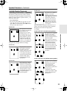
A
PRE OUT A/B
To use the DTR-10.5 as a preamplifier, connect a
power amplifier to this jack.
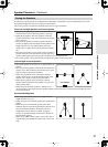
B
SPEAKERS A/B
These terminals are for connecting the speakers.
Two sets of home theater connections are available
(simultaneous playback of different sources in each
of two home theaters is not supported).
Depending on your system, various speaker
connections will be available. For example, you can
use the surround back speakers for playback in a
different room.
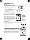
C
AC OUTLET
The DTR-10.5 is equipped with AC mains outlet for
connecting the power cords from other devices so
that their power is supplied through the DTR-10.5.
By doing this, you can leave the connected device
turned on and have the [Standby/On] button on the
DTR-10.5 turn on and off the device together with
the DTR-10.5.
The shape and total capacity of the AC outlets
may differ depending on the area of purchase.
Caution:
Make sure that the total capacity of the components
connected to the DTR-10.5 does not exceed the
capacity that is printed on the rear panel (e.g., AC
120V - 60Hz SWITCHED 120W 1A MAX.).
D
AC INLET
This connector is for connecting the supplied power
cord.
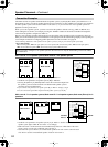
E
IR IN
These connectors are for connecting the remote
sensor of a multiroom kit (sold separately).
The connectors are provided for main room, Zone 2,
and Zone 3.
Getting Started