


32
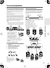
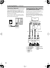
Connecting AV Components
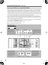
In addition to the conventional terminals, the DTR-10.5 has various terminals that are capable of next-generation digital
transmission.
Before connecting AV components to the DTR-10.5, make sure that your cable type matches the terminal shape and the
signal type and that the cable length is appropriate for the placement of your connected components.
Audio cables
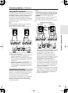
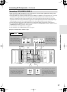
*The audio input signal from the ETHERNET (Net-Tune) or MULTI-CH IN terminal will not be output to the HDMI
OUT terminal. Also, the DVD audio or SACD audio input signal from the i.LINK (AUDIO) terminal will not be output
to the HDMI OUT terminal.
When you play a source in the remote zone (Zone 2 or Zone 3), the following restrictions are applied.
• When you play the audio signal from Super Audio CD or DVD-Audio format sources through the i.LINK (AUDIO)
interface, the audio input signal from these sources will not be output to Zone 2 or Zone 3. With this connection, you
cannot record from these sources.
• When you play the audio signal from the i.LINK (AUDIO) interface in Zone 3, only the PCM signal will be output
as an analog source to the AUDIO OUT terminals. Similarly, with this connection, you can record only the PCM sig-
nal as an analog source through the AUDIO OUT terminals.
• The audio input signal from the LAN port will be output only to the AUDIO OUT terminals as an analog source.
• When you play the audio signal from the PH or AUDIO IN terminals in Zone 3, the input source will be output only
to the AUDIO OUT terminals as an analog source. Similarly, in this connection, you can record only the audio signal
as an analog source through the AUDIO OUT terminals.
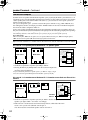
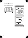
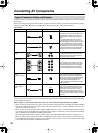
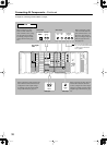
Types of Connection Cables and Terminals
Cable names Cable forms Terminals shapes Description
Optical cable
The connection using these cable types trans-
mits digital audio signals. There is no sound
quality difference among these cable types.
Note:
Some optical cables have their own covers.
Before making a connection, remove the cov-
ers. When plugging in a cable, be sure to match
the connector shape with the terminal shape.
Each optical terminal on the DTR-10.5 has its
own shutter-type cover. For the DTR-10.5, plug
in the optical cables so that the optical cable
connector pushes the terminal cover down.
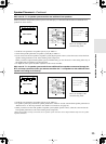
Coaxial cable
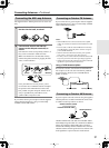
Audio connection
cable
This connection transmits an analog audio sig-
nal. Plug the red connector (R) into the right
channel terminal and the white connector (L)
into the left channel connector.
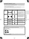
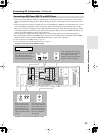
Multichannel con-
nection cable
For USA and Canadian models, this terminal
board is optional. The terminals for this cable
type are for DVD players that are compatible
with the DVD-Audio format. This connection
transmits multichannel analog audio signals.
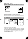
i.LINK connection
cable
(4-pin (S400) type)
This terminal board is optional. This connection
can be used for connecting i.LINK (AUDIO)-
enabled devices and to transmit digital audio
signals. Also, multichannel analog audio signals
from DVD-Audio or Super Audio CD format
sources will be transmitted digitally. The
DTR-10.5 handles only audio signals through
i.LINK connection.
Ethernet cable
(CAT-5 Straight
type)
This terminal board is optional. The Ethernet
cable is used for connecting multiple PCs or
network-ready audio components that consti-
tute a local area network (LAN). A LAN is a
smaller network composed within a house or
building. The connecting terminals for the Ether-
net cables are often called “LAN port” or “broad-
band port.”
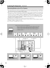
SBR SBL
SR SL
SUB C
FR
FL
MULTI
-
CH
IN
1
ETHERNET
(
Net
-
Tune
)