


49
Installation and Connections
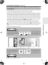
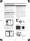
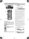
Using an External Device with 12V Trigger Terminal
You can turn on the AV devices connected to the
DTR-10.5 automatically using the output signal from the
12V TRIGGER OUT terminal on the DTR-10.5.
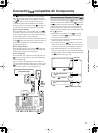
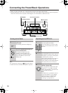
Making a Connection
You can connect up to five devices to the 12V TRIGGER
Phoenix (Pluggable Connector) terminal (larger one)
and one device to the 12V TRIGGER OUT E terminal
(mini-jack).
You can connect any external devices to the DTR-10.5
whether the connected device is located in the main,
Zone 2 or Zone 3 room.
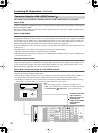
There are five terminals for connecting external
devices and their maximum current allowed to be
connected are as follows:
A:
Up to 200 mA.
B, C and D:
Up to 100 mA each.
E:
Up to 100 mA for the total current value of both the
Phoenix and mini-jack terminals.
Before connecting an external device, check that the cur-
rent value for the 12V TRIGGER terminal of the con-
nected device does not exceed the target terminal’s
maximum current above.
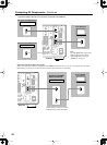
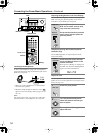
When using the 12V TRIGGER Phoenix (Pluggable
Connector) terminal:
1. Loosen the screws using a flatblade screwdriver to
open the shutters.
2. Connect the GND wire (black) to the GND terminal,
and close the shutter.
3. Connect the remaining wire to any of the terminals
between A and E, and close the shutter.
4. When you connect more than one external device,
you can connect all the GND wires to the GND ter-
minal together.
5. Connect the Phoenix terminal firmly to the 12V
TRIGGER OUT socket on the DTR-10.5.
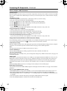
6. After making connections, you have to configure the
association between the room where the device is
used and the device to be turned on. For performing
this setting, refer to “12V Trigger Assign” of “Input
Setup” section on page 98.
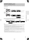
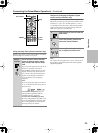
When using the mini-jack 12V TRIGGER OUT E
terminal:
When you want to connect two devices to both the Phoe-
nix terminal E and mini-jack terminal simultaneously,
you can connect them as long as the total current value of
their 12V TRIGGER terminals will not exceed 100 mA
.
A
B
C
GND
D
E
Flatblade
screwdriver
Wire
A
B
C
GND
D
E
200mA MAX
100mA MAX
100mA MAX
100mA MAX
TOTAL 100mA MAX
L
R
L
R
FRONT
CENTER
SURR
SURR
BACK
SUB
WOOFER
SURR BACK R
SURR R FRONT R CENTER FRONT L
SURR BACK L
SURR L
SUBWOOFER
PRE
OUT A
(
ASSIGNABLE
)
(
SINGLE
)
(
SINGLE
)
(
ASSIGNABLE
)
(
ASSIGNABLE
)
“Net
-
Tune”
is
a
trademark
of
Onkyo
Corporation.
ETHERNET
(
Net
-
Tune
)
AUDIO
The
i.LINK
logo
is
a
trademarks
of
Sony
Corporation, registered
in
the
U.S.
and
other
countries.
S400
22
11
66
55
44
33
22
11
C D
DIGITAL IN DIGITAL IN
OPTICAL COAXIAL
OUT
SBR SBL
SR SL
SUB C
FR FL
SBR SBL
SR SL
SUB C
FR
FL
E
MULTI
-
CH
IN
1
MULTI
-
CH
IN
2
AUDIO IN
1
3
2
1
PH
2
3
9
8
7
6
5
4
4
5
LRRL
GND
OUT
LR
LR
R L
F
G
L
IN
1
IN
2
HDMI, the HDMI logo
is a trademark
or registered
trademarks of HDMI
Licensing LLC.
OUT
HDMI
S
VIDEO VIDEO
IN IN
IN
1
IN
2
3
2
1
Y
PB
PR
COMPONENT
VIDEO
IN
3
IH
6
5
4
Y
P
B
PR
2
1
4
3
S VIDEOS VIDEO VIDEOVIDEO
OUT OUT
OUT
1
J
Y
P
B
PR
Y
P
B
PR
COMPONENT VIDEO
IN
4
OUT
K
ANTENNA
FM
75
AM
L
R
L
R
CENTER
SURRFRONT
SURR
BACK
SUB
WOOFER
PR
E
OUT
B
AC
INLET
MODEL NO.
RDC
-
7.1
(
ASSIGNABLE
)
(
SINGLE
)
A B
UDD
RS
232
GND
C
D
E
B
A
12
V
TRIGGER
OUT
100mA MAX.
100mA MAX.
100mA MAX.
TOTAL
100mA MAX.
200mA MAX.
12 V
TRIGGER
OUT
E
IR
IN
+
12
V DC PWR SUPPLY
MAIN
GND
ZONE
3
ZONE
2
20mA MAX.
Push the connector
into the socket until
it clicks.
E
GND
“Net
-
Tune”
is
a
trademark
of
Onkyo
Corporation.
ETHERNET
(
Net
-
Tune
)
A
RS
232
IR
IN
+
12
V DC PWR SUPPLY
MAIN
GND
ZONE
3
ZONE
2
20mA MAX.
12 V
TRIGGER
OUT
E
MODEL NO.
DTR
-
10.5
GND
C
D
E
B
A
12
V
TRIGGER
OUT
100mA MAX.
100mA MAX.
100mA MAX.
TOTAL
100mA MAX.
200mA MAX.
UDD
AC
INLET
A
L
R
FRONTSURR SURR
BACK
CENTER
SUB
WOOFER
SUB
WOOFER
FRONT
L
CENTERFRONT
R
SURR BACK
L
(
ASSIGNABLE
)
SURR
R
SURR
L
FRONT
R
(
BTL
)
FRONT
L
(
BTL
)
PRE
OUT
A
(
SINGLE
)
PRE
OUT B
AC 120V 60Hz
SWITCHED
120W 1A MAX.
AC
OUTLET
SPEAKERS A
SPEAKERS B
22
1
66
55
44
33
22
11
OPTICAL COAXIAL
AUDIO IN
1
3
2
1
PH
2
3
9
8
7
6
5
4
4
5
RL
LR
LR
R L
G
IN
1
IN
2
HDMI
S
VIDEO VIDEO
IN IN
IN
1
IN
2
3
2
1
Y
P
B
P
R
COMPONENT
VIDEO
IN
3
6
5
4
Y
P
B
P
R
2
1
4
3
ANTENNA
FM
75
B
SURR BACK
R
(
ASSIGNABLE
)
DIGITAL IN DIGITAL IN
LR
S VIDEOS VIDEO VIDEOVIDEO
CD
OUT
OUT
F
L
OUT
IH
OUT OUT
J
K
OUT
1
AM
1
SBR SBL
SR SL
SUB C
FR FL
SBR SBL
SR SL
SUB C
FR
FL
MULTI
-
CH
IN
1
MULTI
-
CH
IN
2
B
OUT
Y
P
B
P
R
Y
P
B
P
R
COMPONENT VIDEO
IN
(
HD/BNC
)
RS
232
IR
IN
+
12
V DC PWR SUPPLY
MAIN
GND
ZONE
3
ZONE
2
20mA MAX.
12 V
TRIGGER
OUT
E
12V TRIGGER
IN
Device