


48
Connecting Components not Reached by the Remote
Controller Signals (IR IN)
In order to use the remote controller to control the
DTR-10.5 from a remote location, you will need to
prepare a multiroom kit (sold separately) such as one
listed below:
• Multiroom kits such as those made by Niles
®
and
Xantech
®
RF Receivers can also be used with the remote controller
to control the DTR-10.5 from a remote location. To use
RF Receivers, set the Transmission Signal Format set-
ting to “RF” (See page 141 for details).
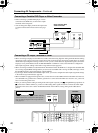
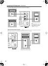
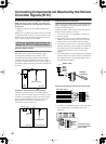
Effective Sensor Layout
Example for the main room
If the DTR-10.5 is located inside a cabinet or other
enclosure where the infrared rays from the remote
controller cannot enter, then operation with the remote
controller will not be possible. In such a case, it will be
necessary to install a remote sensor at a location outside of
the cabinet so that the infrared rays from the controller can
be sensed.
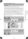
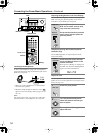
Example for the remote zone (Zone 2/Zone 3)
The IR IN input allows you to control the DTR-10.5
from the remote zone (Zone 2/Zone 3) with the remote
controller even though the remote zone may be on the
other side of the building from the main zone. The
diagram below shows how to make the proper
connections for the remote zone.
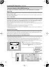
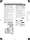
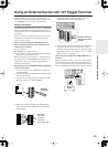
Effective Sensor Connections
When connecting a multiroom kit, use the IR connection
Phoenix (Pluggable connector) terminal (smaller one)
supplied with the DTR-10.5.
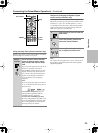
Connect the ribbon cable from the connecting block to
the IR connection Phoenix terminal.
1. Loosen the screws using a flatblade screwdriver to
open the shutters.
2. Connect the white wire to the MAIN, ZONE 2 or
ZONE 3 terminal according to the room where the
multiroom kit is used, and then close the shutter.
3. Connect the red wire to the +12V terminal, and then
close the shutter. If you use more than one multiroom
kit in different rooms such as MAIN and ZONE 2,
connect all the red wires to the +12V terminal
together.
4. Connect the black wire to the GND terminal, and then
close the shutter. If you use more than one multiroom
kit in different rooms, connect all the black wires to
the GND terminal together.
When the multiroom kits are used for all the rooms
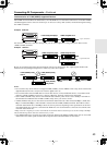
5. As shown in the illustration below, connect the Phoe-
nix terminal firmly to the IR IN socket on the
DTR-10.5.
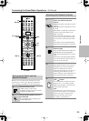
If Remote Controller Signal Does not
Reach the DTR-10.5 Remote Sensor
Connecting
block
IR Receiver
Remote controller
IR IN
DTR-10.5
In the
cabinet
: Signal flow
Main room
IR Receiver
Remote controller
Connecting
block
DTR-10.5
Main room Zone 2/Zone 3 room
: Signal flow
To IR IN
+12V
IN
GND
Flatblade
screwdriver
Red
Black
White
Ribbon cable
+12V
MAIN
GND
ZONE 3
ZONE 2
From Main room
Red
White
Red
White
Red
White
ZONE 2
ZONE 3
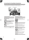
E
GND
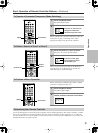
“Net
-
Tune”
is
a
trademark
of
Onkyo
Corporation.
ETHERNET
(
Net
-
Tune
)
A
RS
232
IR
IN
+
12
V DC PWR SUPPLY
MAIN
GND
ZONE
3
ZONE
2
20mA MAX.
12 V
TRIGGER
OUT
E
MODEL NO.
DTR
-
10.5
GND
C
D
E
B
A
12
V
TRIGGER
OUT
100mA MAX.
100mA MAX.
100mA MAX.
TOTAL
100mA MAX.
200mA MAX.
UDD
AC
INLET
A
L
R
FRONTSURR SURR
BACK
CENTER
SUB
WOOFER
SUB
WOOFER
FRONT
L
CENTERFRONT
R
SURR BACK
L
(
ASSIGNABLE
)
SURR
R
SURR
L
FRONT
R
(
BTL
)
FRONT
L
(
BTL
)
PRE
OUT
A
(
SINGLE
)
PRE
OUT B
AC 120V 60Hz
SWITCHED
120W 1A MAX.
AC
OUTLET
SPEAKERS A
SPEAKERS B
22
1
66
55
44
33
22
11
OPTICAL COAXIAL
AUDIO IN
1
3
2
1
PH
2
3
9
8
7
6
5
4
4
5
RL
LR
LR
R L
G
IN
1
IN
2
HDMI
S
VIDEO VIDEO
IN IN
IN
1
IN
2
3
2
1
Y
P
B
P
R
COMPONENT
VIDEO
IN
3
6
5
4
Y
P
B
P
R
2
1
4
3
ANTENNA
FM
75
B
SURR BACK
R
(
ASSIGNABLE
)
DIGITAL IN DIGITAL IN
LR
S VIDEOS VIDEO VIDEOVIDEO
CD
OUT
OUT
F
L
OUT
IH
OUT OUT
J
K
OUT
1
AM
1
SBR SBL
SR SL
SUB C
FR FL
SBR SBL
SR SL
SUB C
FR
FL
MULTI
-
CH
IN
1
MULTI
-
CH
IN
2
B
OUT
Y
P
B
P
R
Y
P
B
P
R
COMPONENT VIDEO
IN
(
HD/BNC
)
Push the connec-
tor into the socket
until it clicks.