


46
Connecting AV Components
—Continued
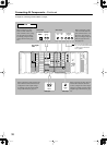
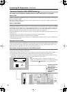
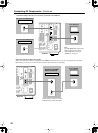
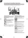
Connection example when the source selection is performed on the DTR-10.5
HDMI
IN
HDMI
OUT
HDMI
OUT
RS
232
IR
IN
+
12
V DC PWR SUPPLY
MAIN
GND
ZONE
3
ZONE
2
20mA MAX.
12 V
TRIGGER
OUT
E
MODEL NO.
DTR
-
10.5
GND
C
D
E
B
A
12
V
TRIGGER
OUT
100mA MAX.
100mA MAX.
100mA MAX.
TOTAL
100mA MAX.
200mA MAX.
UPA
AC
INLET
E
)
SURR
L
AC 230-240V 50Hz
SWITCHED 100W MAX.
AC
OUTLET
SPEA-
KERS A
SPEA-
KERS B
IN
1
IN
2
HDMI
Y
P
B
P
R
E
NT
Y
P
B
P
R
ANTENNA
FM
75
O
L
OUT
J
K
AM
OUT
Y
P
B
P
R
Y
P
B
P
R
COMPONENT VIDEO
IN
(
HD/ BNC
)
RS
232
IR
IN
+
12
V DC PWR SUPPLY
MAIN
GND
ZONE
3
ZONE
2
20mA MAX.
12 V
TRIGGER
OUT
E
MODEL NO.
DTR
-
10.5
GND
C
D
E
B
A
12
V
TRIGGER
OUT
100mA MAX.
100mA MAX.
100mA MAX.
TOTAL
100mA MAX.
200mA MAX.
A
AC
INLET
SURR
L
AC 230-240V 50Hz
SWITCHED 100W MAX.
AC
OUTLET
SPEA-
KERS A
SPEA-
KERS B
IN
1
IN
2
HDMI
ANTENNA
FM
75
L
OUT
K
AM
OUT
Y
P
B
P
R
Y
P
B
P
R
O
NENT VIDEO
IN
HDMI
IN
HDMI
IN
HDMI
OUT
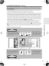
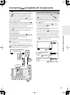
Before making a connection, read the
DVD instruction manual thoroughly.
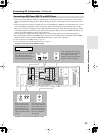
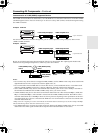
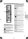
Connection example for higher video quality
When connecting an AV component equipped with the HDMI input terminal, you can use the connecting layout shown below.
Before making a connection, read the instruction manual of the connected device thoroughly.
DVD Player with HDMI
INPUT and OUTPUT
TV or Projector
DTR-10.5
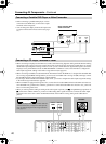
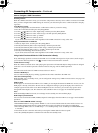
TV or Projector
DVD Player with HDMI OUTPUT
Set Top Box with HDMI OUTPUT
DTR-10.5
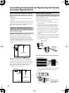
Tips:
To enable HDMI audio output of the
DTR-10.5 from the TV speakers,
enable HDMI Out according to
“HDMI Out” on page 92.