


14
En
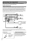
Connecting Your Equipment
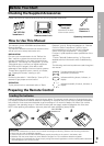
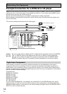
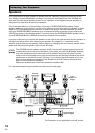
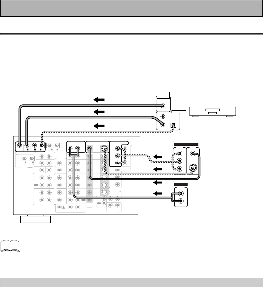
Example Connection for a DVD/LD or LD player
Make sure you connect your DVD/LD or LD players using both the 2 RF jack and either a coaxial or
optical (you don't need to do both of these) digital connections. If your player has an 2 RF output
this will ensure you can use all LDs (see p.15).
We also recommend hooking up your digital components to analog audio jacks.
Before making or changing the connections, switch off the power and disconnect the power cord
from the AC outlet.
*The arrows indicate the direction of the video signal.
memo
CD
IN
R
L
R
L
MD /
TAPE1/
CD-R
PLAY
REC
TAPE2
MONITOR
PLAY
REC
IN
PHONO
MONITOR
OUT 2
MONITOR
OUT 1
SURR-
OUND
SUB
WOOFER
CENTER
FRONT
MULTI CH IN
SURR-
OUND
FRONT
SUB
WOOFER
PRE OUT
CENTER
RL
L
R
R
L
R
L
R
RL
L
(Songle)
COMPONENT VIDEO
DVD/LD
IN
TV/SAT
IN
Y
P
B
P
R
MONITOR
OUT
P
B
P
R
Y
MULTI CH IN
SURROUND
BACK
SURROUND
BACK
PRE OUT
DVD /
LD
IN
S VIDEOVIDEO
VIDEOAUDIO
IN
TV /
SAT
IN
IN
OUT
IN
VCR1 /
DVR
OUT
IN
OUT
IN
VCR2
OUT
IN
CONTROL
IN
OUT
PCM /
2
/ DTS/ MPEG
DIGITAL
IN
5
IN
4
IN
3
2
RF IN
(AC-3)
IN
2
IN
1
LINE/
TUNER
IN
AUDIO
OUTOUT
21
DVD/LD player
or LD player
1
23
DIGITAL OUT
(AC-3)(LD)
RF OUT
2
COMPO-
NENT
VIDEO
OUT
VIDEO
S-VIDEO
P
B
Y
P
R
STEREO
L
R
ANALOG
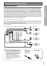
Digital Input Assignment
Unlike analog connections, the jacks for digital connections are not dedicated to one type of
component, they can be used freely. Thus you must tell the amplifier what digital component in
which jack so your components will be in sync with the names on the remote control buttons and
the like. To avoid having to assign the digital inputs you can hook up your equipment in accordance
with the amplifier's default settings.
The default are:
DIGITAL IN 1: DVD/LD
DIGITAL IN 2: CD
DIGITAL IN 3: MD
DIGITAL IN 4: TV/SAT
DIGITAL IN 5 VCR1
AC-3 RF: DVD/LD
You will notice that Digital IN 1, for example, is a coaxial jack. If your DVD/LD player only has an
optical out jack on it then you won't be able to hook up your components in accordance with the
VSA-E08's default setting. In this case you will need to assign the digital inputs. See DIGITAL INPUT
SELECT on p.31 in order to do this.
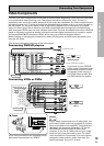
Be sure to make either a digital coaxial or digital optical connection (pictured as DIGITAL
jack 1 or DIGITAL jack 3 in this diagram) as well, but you DON'T need to make both.
Also, be sure to assign the jacks to the proper component(s) with the DIGITAL INPUT
SELECT procedure (see p.31) if necessary. See the explanation on the left for details.
(not a PCM-only output)