


21
Connecting to Audio/Video Equipment—Continued
For other models:
Note that the OSD Menu data will be output to the
MONITOR OUT VIDEO, S VIDEO and
COMPONENT VIDEO jacks. When you connect any
OSD-specific monitor TV to the VIDEO connectors, you
can disable the OSD output to COMPONENT VIDEO
OUTPUT. To disable the OSD output, select Setup
Menu → Preference → OSD Setup → Component
Video, and then select “OSD Off” (See page 63).
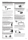
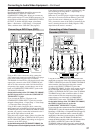
Using an RCA video connection cable, connect the
video output jack (composite) of the DVD or LD player
to the DVD VIDEO IN jack of the TX-NR801/
TX-NR801E. Or if the DVD or LD player has an S video
output jack, connect it to the DVD S VIDEO IN jack
with an S video connection cable. Or if the device has
component video outputs, connect them to one of the
banks of COMPONENT VIDEO INPUT jacks on the
TX-NR801/TX-NR801E.
On the initial settings of the TX-NR801/TX-NR801E,
the DVD input source is set for the COMPONENT
VIDEO INPUT 1 jacks.
If you connect the DVD or LD player to the
COMPONENT VIDEO INPUT 2 jacks, this must be
changed at Setup Menu → Input Setup → Video Setup
→ Component Video (See page 38).
Using an RCA audio connection cable, connect the
audio output jacks of the DVD or LD player to the DVD
AUDIO IN jacks of the TX-NR801/TX-NR801E. Make
sure that you properly connect the left channel to the L
jack and the right channel to the R jack.
If the device has a digital output, connect it to either the
DIGITAL IN COAX jack or DIGITAL IN OPT jack of
the TX-NR801/TX-NR801E, depending on the type of
connector on the DVD player.
On the initial settings of the TX-NR801/TX-NR801E, the
DVD input source is set for digital input at the COAX 1 jack.
If the digital connection is made at a different jack, this
must be changed at Setup Menu → Input Setup →
Digital Setup (See page 36).
Make sure of your DVD player’s digital output settings.
You need to access the On Screen Menu of your DVD
player. See the owner’s Manual on your DVD player.
Also, you need to aware of the Table of contents for the
movie, selecting the movie for Dolby Digital or DTS,
depends how the movie is encoded.
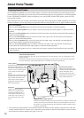
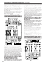
Using RCA video connection cables, connect the video
output jack (composite) of the video cassette recorder to the
VIDEO 1 VIDEO IN jack of the TX-NR801/TX-NR801E
and connect the video input jack of the video cassette
recorder to the VIDEO 1 VIDEO OUT jack of the
TX-NR801/TX-NR801E. Or if the video cassette recorder
has S video input and output jacks, connect them to the
VIDEO 1 S VIDEO IN and OUT jacks of the TX-NR801/
TX-NR801E using S video connection cables. Or if the
video cassette recorder has component video outputs,
connect them to one of the banks of COMPONENT
VIDEO INPUT jacks on the TX-NR801/TX-NR801E.
On the initial settings of the TX-NR801/TX-NR801E,
the VIDEO 1 input source is set for the
COMPONENT VIDEO INPUT 2 jacks.
If you connect the video cassette recorder to the COMPONENT
VIDEO INPUT 1 jacks, this must be changed at Setup Menu →
Input Setup → Video Setup → Component Video (See page 38).
Using RCA audio connection cables, connect the audio
output jacks of the video cassette recorder to the VIDEO 1
AUDIO IN jacks of the TX-NR801/TX-NR801E and
connect the audio input jacks of the video cassette recorder to
the VIDEO 1 AUDIO OUT jacks of the TX-NR801/
TX-NR801E. Make sure that you properly connect the left
channels to the L jacks and the right channels to the R jacks.
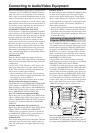
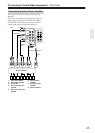
Connecting a DVD Player (DVD)
AUDIO
VIDEO
S VIDEO
MONITOR
OUT
R
L
IN
IN
IN
IN
IN
ZONE 2
DVD
VIDEO 1
VIDEO 2
VIDEO 3
VIDEO 4
AUDIO
VIDEO
S VIDEO
COMPONENT
VIDEO
Y
P
B
PR
OUTPUT
INPUT 1
Y
P
B
PR
INPUT 2
Y
P
B
PR
R
L
OUT
OUT
OUT
PHONO
DIGITAL
IN
PRE OUT
DIGITAL
OUT
OPT
OPT
2
1
2
1
2
3
FRONT
SUB
SURR
R
L
AUDIO
R
L
CD
TAPE
R
L
AUDIO
1
3
GND
SURR
BACK/
ZONE 2
IN
OUT
COAX
R
L
MULTI
CH
INPUT
FRONT
SUB
SURR
SURR
BACK
CENTER
R
L
R
L
AM
FM
75
CENTER
ANTENNA
IN
IN
Y
P
B
PR
Y
P
B
PR
COMPONENT
VIDEO
INPUT 1
COMPONENT
VIDEO
OUTPUT
R
L
IN
DVD
DIGITAL
IN
AUDIO
VIDEO S VIDEO
COAX
1
R
L
DIGITAL
OUT
AUDIO
OUT
VIDEO
OUT
S VIDEO
OUT
COAX
DVD player
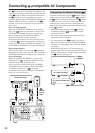
Connecting a Video Cassette
Recorder (VIDEO 1)
AUDIO
VIDEO
S VIDEO
MONITOR
OUT
R
L
IN
IN
IN
IN
IN
ZONE 2
DVD
VIDEO 1
VIDEO 2
VIDEO 3
VIDEO 4
AUDIO
VIDEO
S VIDEO
COMPONENT
VIDEO
Y
P
B
PR
OUTPUT
INPUT 1
Y
P
B
PR
INPUT 2
Y
P
B
PR
R
L
OUT
OUT
OUT
PHONO
DIGITAL
IN
PRE OUT
DIGITAL
OUT
OPT
OPT
2
1
2
1
2
3
FRONT
SUB
SURR
R
L
AUDIO
R
L
CD
TAPE
R
L
AUDIO
1
3
GND
SURR
BACK/
ZONE 2
IN
OUT
COAX
R
L
MULTI
CH
INPUT
FRONT
SUB
SURR
SURR
BACK
CENTER
R
L
R
L
AM
FM
75
CENTER
ANTENNA
IN
IN
IN
VIDEO 1
AUDIO
VIDEO S VIDEO
OUT
RL
AUDIO OUT
VIDEO
OUT
S VIDEO
OUT
RL
AUDIO IN
VIDEO
IN
S VIDEO
IN
RL
VCR