


11
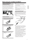
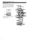
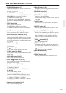
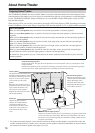
Index Parts and Facilities—Continued
For more information regarding connection procedures,
see pages indicated in brackets [ ].
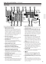
1 DIGITAL IN/OUT [21-24]
These jacks are for connecting components with
digital input and output capabilities. To connect a
CD player, see page 23; to connect an MD or CD
recorder, see page 24; to connect a DAT deck, see
page 24; to connect a DVD player, see page 21; to
connect a DVD recorder, see page 22; and to con-
nect a digital satellite tuner, see page 22.
2 PRE OUT [18, 25, 66]
To use the TX-NR801/TX-NR801E as a preampli-
fier, connect a power amplifier to this jack.
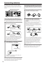
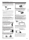
3 ANTENNA [14]
These jacks are for connecting the FM indoor
antenna and the AM loop antenna that are supplied
with the TX-NR801/TX-NR801E.
4 ZONE 2 VIDEO OUT [21, 66]
This jack is for connecting the component that will
be used in the remote zone (Zone 2).
5 MONITOR OUT VIDEO/S VIDEO [20]
These jacks are for connecting to the video input
jacks on television monitors or projectors.
6 COMPONENT VIDEO OUTPUT [20]
These jacks are for connecting to the component
video input jacks on television monitors or projectors.
7 ETHERNET (Net-Tune) [71]
This connector is for connecting to an Ethernet network.
8 SPEAKERS [18, 66]
These terminals are for connecting the speakers.
9 AC OUTLETS [24]
This AC outlet is provided to plug in the power cord
from another component. The shape and number of
the AC outlet depend on the shipping destination.
0 MULTI CH INPUT [64]
This connector is for connecting components with a
multichannel output.
A PHONO/CD/TAPE AUDIO IN/OUT [23, 24]
These connectors are for connecting to the audio
input and output jacks on audio components. To
connect a turntable, see page 24; to connect a CD
player, see page 23; and to connect a cassette tape
deck, MD recorder, or CD recorder, see page 24.
B DVD/VIDEO1-4 IN/OUT [21, 22]
These connectors are for connecting to the video
input and output jacks on video components. To
connect a DVD player, see page 21; to connect a
DVD recorder, see page 22; to connect a VCR, see
page 21; and to connect a digital satellite tuner, see
page 22.
C COMPONENT VIDEO INPUT1/2 [21, 22]
These connectors are for connecting to the compo-
nent video outputs of video components that have
them. To connect a DVD player, see page 21; to
connect a DVD recorder, see page 22; and to con-
nect a digital satellite tuner, see page 22.
D IR IN/OUT [69]
These connectors are for connecting the remote sen-
sor of a multi-room kit (sold separately).
E [26]
This jack is for connecting other Onkyo compo-
nents equipped with the same terminal. The
audio connection cables must also be connected.
F VOLTAGE SELECTOR [7] (Worldwide models
only)
This is only available on the worldwide model.
Before connecting the power cord to the wall outlet,
be sure to set this to the correct power supply volt-
age for your region.
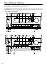
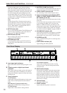
Rear Panel
SURR
BACK/
ZONE 2
SPEAKERS
AUDIO
VIDEO
S VIDEO
MONITOR
OUT
R
L
IN
IN
IN
IN
IN
ZONE 2
DVD
VIDEO 1
VIDEO 2
VIDEO 3
VIDEO 4
AUDIO
VIDEO
S VIDEO
COMPONENT
VIDEO
Y
P
B
PR
OUTPUT
INPUT 1
Y
P
B
PR
INPUT 2
Y
P
B
PR
FRONT SPEAKERS
L
RL
R
SURR SPEAKERS
CENTER
SPEAKER
R
L
R
L
OUT
OUT
OUT
I
R
IN
OUT
REMOTE
CONTROL
PHONO
DIGITAL
IN
PRE OUT
DIGITAL
OUT
OPT
OPT
2
1
2
1
2
3
FRONT
SUB
SURR
R
L
AUDIO
R
L
CD
TAPE
R
L
AUDIO
1
3
GND
SURR
BACK/
ZONE 2
IN
OUT
COAX
R
L
MULTI
CH
INPUT
FRONT
SUB
SURR
SURR
BACK
CENTER
R
L
R
L
AM
FM
75
CENTER
ANTENNA
IN
IN
(
Net
-
Tune
)
ETHERNET
4 OHMS MIN. OR
6 OHMS MIN.
/SPEAKER
CAUTION
:
SPEAKER
IMPEDANCE
SEE INSTRUCTION
MANUAL FOR
CORRECT SETTINGS.
AC OUTLETS
AC
120
V 60
Hz
SWITCHED
TOTAL 120W 1A MAX.
AV RECEIVER
MODEL NO. TX
-
NR
801
VOLTAGE
SELECTOR
220
-
230V
120V