


System Description
6 CineWall™ Installer/Integrator Manual
PRE
L
IMINAR
Y
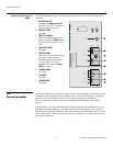
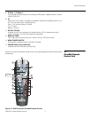
Input Connectors and
LEDs
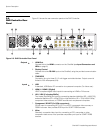
The CineWall interface board is equipped with the following input connectors and LED
indicators:
1. RS-232 (RJ-45)
Connect the Display Control
output on the DHD Controller to
this input (see
Figure 2-3).
2. DIGITAL (DVI)
Not used.
3. DIGITAL (HDMI)
HDCP-compliant digital video
input. Connect the HDMI output
from the DHD Controller to this
input.
4. ANALOG (RG B)
Not used.
5. STATUS LEDs
These provide information about
the current state of various
CineWall system components.
For information on how to
interpret them, refer to
Status
LEDs on page 77.
6. COMPONENT
Not used.
7. S-VIDEO
Not used.
8. COMPOSITE
Not used.
2.2
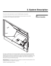
Screen Assembly
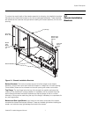
The Screen Assembly comprises all of the components associated with the screen which
is attached on the outer side of the installation wall. The Screen Assembly is packaged
separately from the Chassis Assembly, to facilitate unpacking and installation.
Southco-type latches at the bottom of the screen secure the screen in the closed
position.
A hinge system is provided at the top of the screen assembly that interfaces to the top
flange of the chassis assembly. This hinge allows the screen assembly to be “hooked”
from the top during initial installation. Two, small retaining brackets attach to the top rear
of the screen frame. These prevent the screen from “hopping” out of the hinge hook and
thus secure the screen.
➤
Fan - System
Fan - DMD
Fan - Lamp
Ballast Status
Engine Status
Lamp Saver
Serial Cmd
Serial Data
Remote IR
Lamp
Source
Ready
Option Key
DVI TO ENGINE
POWER +5V OUT IR SENSOR CUBE CONTROL
ICP AUX
RS-232
DIGITAL DVI
DIGITAL HDMI
ANALOG
COMPONENT
S-VIDEO
COMPOSITE
INPUT
RS-232
1
2
3
4
5
6
7
8