


Design Guide for the Polycom SoundStructure C16, C12, C8, and SR12
3 - 22
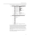
The value of the digital control array is the binary sum of the individual logic
pins. For example if a control array virtual channel is defined with digital
output pins 3, 2, and 1, then the value of the control array channel will be in
the range of 0 to 7 with physical logic output pin 3 as the most significant bit
and physical logic output pin 1 as the least significant bit.
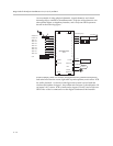
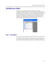
A control array named “logic array” that uses physical logic input pins 2, 3,
and 4 may be created with the following syntax:
vcdef “logic raray” control_array digital_gpio_in 4 3 2
which will return the command acknowledgement:
vcdef "logic array" control_array digital_gpio_in 4 3 2
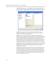
The value of the digital input array can be queried using the get action:
get digital_gpio_value "logic array"
val digital_gpio_value "logic array" 0
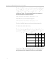
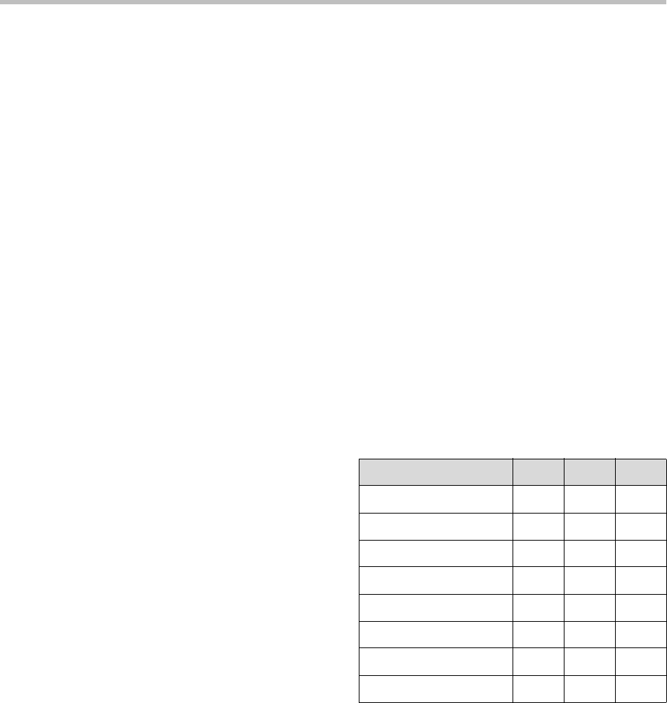
The value of the logic array will depend on the state of inputs 4, 3, and 2 as
shown in the following table. The order that the pins are listed in the control
array definition is defined so that the first pin specified is the most significant
bit and the last pin specified is the least significant bit.
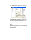
A control array of logic output pins may be specified with the same syntax as
in the previous example substituting digital_gpio_out for digital_gpio_in.
See Appendix A for more information on control array virtual channels.
Control Array Value Pin 4 Pin 3 Pin 2
0000
1001
2010
3011
4100
5101
6110
7111