


Design Guide for the Polycom SoundStructure C16, C12, C8, and SR12
9 - 6
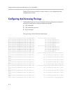
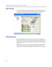
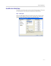
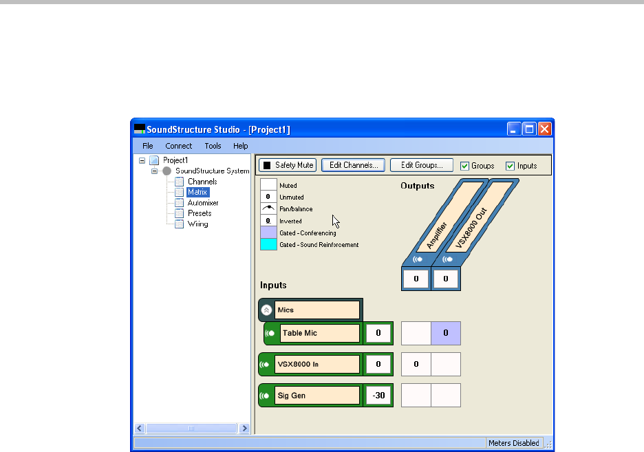
Matrix Settings
The matrix page shows how the input signals are mapped to the output sig-
nals. In this example, the tabletop microphone is sent to the VSX8000 and the
VSX8000 is sent to the local amplifier. The signal generator is muted.
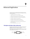
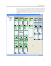
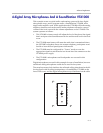
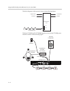
Wiring Information
The system should be cabled according to the layout on the wiring page as
shown in the following figure. To wire the system with virtual channels on dif-
ferent physical inputs or outputs, drag the channels to their desired physical
inputs or outputs and then cable the system according to the updated wiring
information.
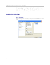
In this example, Table Mic 1 is connected to physical input 1, the VSX8000 In
channel is connected to physical input 1, the VSX8000 Out channel is con-
nected to physical output 1 and the Amplifier channel is connected to physical