


Design Guide for the Polycom SoundStructure C16, C12, C8, and SR12
7 - 10
Configuring The Signal Gains
Once the SoundStructure device settings are synchronized with SoundStruc-
ture Studio, either by uploading or downloading a configuration file, the next
step is to ensure the input signals have the proper analog gain to get to the 0
dBu nominal signal level of the SoundStructure devices.
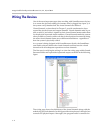
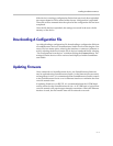
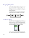
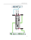
SoundStructure devices may have gain applied in various positions through-
out the signal chain as shown in the following figure. Gain may be applied in
the analog input gain stage, the input fader, the matrix, the output fader, and
the output analog gain stage.
The analog input gain is applied in the analog domain to the analog input
signal to adjust the signal level to match the level required by the Analog to
Digital converter to properly digitize the signal with the required signal
fidelity.
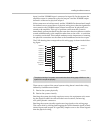
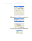
Input Signal Level Adjustment
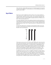
The analog input gains are adjusted with the input gain slider on the Sound-
Structure Studio channels page. Any slider adjustments cause the mic_in_gain
command to be executed. The analog input gain slider provides an adjustable
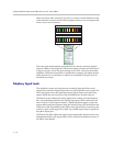
range from -20 to +64dB of gain in 0.5dB gain steps and has a meter that shows
the input signal activity from -20 to +20 dBu as shown in the following figure.
The purpose of the analog input gain is to provide enough gain to get the input
signal to the 0 dBu nominal signal level of the SoundStructure devices and
have additional headroom for the signal to peak above that level.
The input signal meter is labeled so that signals greater than -20dB will light
the first meter segment, greater than -16dB will light the second meter seg-
ment,..., and finally greater than +16 will light the tenth meter segment. In this
A/D
Input
Processing
Output
Processing
D/A
Analog Input Analog Output
Analog Gain Analog Gain
Input Fader Output Fader
Matrix
Digital Processing
-12
-8
-4
0
4
8
12
16
+20
-20
-16