


Design Guide for the Polycom SoundStructure C16, C12, C8, and SR12
6 - 14
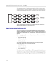
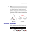
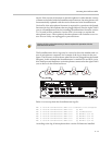
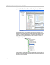
The following table shows the number of analog inputs that are available
based on the number of microphone arrays that are used in a system. As an
example, a SoundStructure C16 supports 16 analog inputs. When used with
two microphone arrays, 10 analog inputs are still available for use with other
analog inputs including microphones, program audio, etc.
Digital Microphone Firmware Updates
When the digital microphone arrays are connected directly to the SoundStruc-
ture device, the version of firmware on the microphones will be compared to
the version of microphone firmware included within the SoundStructure
C16 C12 C8
0
16 12 8
1
13 9 5
2
10 6 2
3
73--
4
40--
# of available analog inputs
with SoundStructure
# HDX
microphones
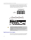
PIN 2: TXD
PIN 3: RXD
PIN 5: GROUND
PIN 7: CTS
PIN 8: RTS
LAN
C-LINK2
OBAM IR
RS-232
REMOTE CONTROL 2
IN OUT
1 2 3 4 5 6 7 8 9 10 11 12 13 14 15 16
1 2 3 4 5 6 7 8 9 10 11 12 13 14 15 16
OUTPUTS INPUTS
SoundStructure C16
TM
12V
REMOTE CONTROL 1
POLYCOM POLYCOM
POLYCOM
POLYCOM
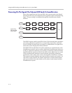
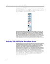
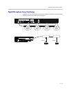
In SoundStructure only applications, connect the digital array microphones to the
right CLink2 port (the port closest to the OBAM interface).
In SoundStructure and HDX applications, connect the HDX to the left CLink2 port
on SoundStructure and connect digital microphones to either CLink2 port on the
HDX system.
Version 2.0.1 of HDX supports 3 microphone arrays when connected to the
SoundStructure device over CLink2.