


Design Guide for the Polycom SoundStructure C16, C12, C8, and SR12
3 - 8
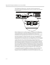
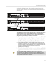
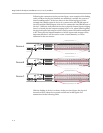
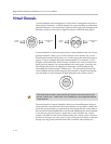
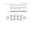
finally device B becomes the third device in the link. The result is that the
inputs and outputs on device C will become inputs 17-32 and outputs 17-32 on
the full system even though device B is physically installed on top of device C.
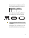
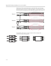
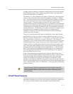
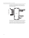
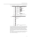
Conceptually, this creates a system as shown in the next figure and
summarized in the following table.
PIN 2: TXD
PIN 3: RXD
PIN 5: GROUND
PIN 7: CTS
PIN 8: RTS
OBAM IR
RS-232
REMOTE CONTROL 2
REMOTE CONTROL 1
IN OUT
OUTPUTS INPUTS
SoundStructure C16
TM
12V
PIN 2: TXD
PIN 3: RXD
PIN 5: GROUND
PIN 7: CTS
PIN 8: RTS
OBAM IR
RS-232
REMOTE CONTROL 2
REMOTE CONTROL 1
IN OUT
OUTPUTS INPUTS
12V
PIN 2: TXD
PIN 3: RXD
PIN 5: GROUND
PIN 7: CTS
PIN 8: RTS
OBAM IR
RS-232
REMOTE CONTROL 2
REMOTE CONTROL 1
IN OUT
1 2 3 4 5 6 7 8 9 10 11 12 13 14 15 16
OUTPUTS INPUTS
12V
Output Physical Channels 1 - 16
Input Physical Channels 17 - 32
Output Physical Channels 17 - 32
Device A
Device B
Device C
16 16
A
IN
OUT
OBAM
16 16
B
16
16
16
16
16
16
16
16
C
A
B
C
A
B
C
IN
OUT
OBAM
IN
OUT
OBAM
1
16
17
32
33
48
1
16
17
32
33
48