


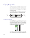
Design Guide for the Polycom SoundStructure C16, C12, C8, and SR12
7 - 14
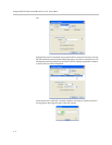
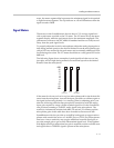
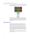
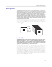
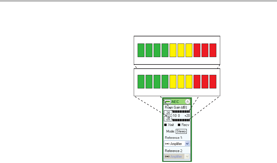
When two mono AEC references are used, or a stereo virtual channel is used
as the reference as shown in the following figure, there are two room gain indi-
cators, one for each reference.
The room gain measurements and guidelines for the two reference applica-
tions are similar to the single AEC reference example. If either reference shows
a high room gain, review the gain settings for the AEC references and audio
amplifier, check the microphone to loudspeaker coupling, and adjust remote
audio input levels as necessary to achieve an acceptable room gain level, as
described previously.
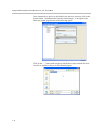
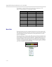
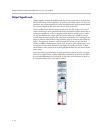
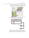
Telephony Signal Levels
The telephony inputs and outputs have an analog input gain that can be
adjusted to create the required signal level on the telephone receive path. The
following figure shows the input and output signal meters and where they
appear within the user interface of the SoundStructure Studio software.
The Phone In gain adjusts the analog signal level coming in from the phone
line. Any adjustments made to the analog input gain will be reflected in the
meter activity of the Phone In channel. Adjust the phone in gain so that the
remote talkers peak level lights at least the second yellow LED and flickers the
LEDs above that. Depending on the PBX or the Central Office connection, this
could be a gain in the range of 0 to 6dB. Up to 20dB of gain may be applied at
the phone input gain.
The Phone Out fader adjusts the signal level transmitted to the phone line. Any
adjustments made to the output fader will be reflected in the meter activity of
the Phone Out channel.
-10 -7 -4 -1 2 5 8 11 14 17
-10 -7 -4 -1 2 5 8 11 14 17