SoundStructure Product Family
2 - 13
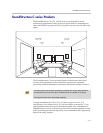
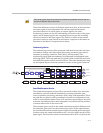
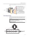
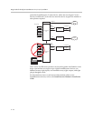
The following figure highlights how to interpret the matrix crosspoints in the
matrix.
C-Series Output processing
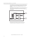
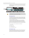
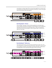
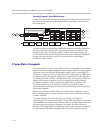
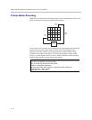
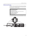
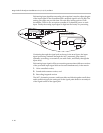
As shown in the following table and figure, each output signal from the matrix
can be processed with dynamics processing, either 10-band parametric or 10-,
15-, or 31-band graphic equalization, a fader, and output delay up to 1000
milliseconds.
Outputs
Ungated/Recording
Conferencing
Sound Reinforcement
Ungated/Recording
Conferencing
Sound Reinforcement
Ungated/Recording
Conferencing
Sound Reinforcement
Ungated/Recording
Conferencing
Sound Reinforcement
Inputs
Crosspoint background indicates
version of input processing
White - Ungated/Recording
Blue - Conferencing (C-series),
Noise cancelled (SR-series)
Light Blue - Sound Reinforcement
Value of crosspoint is the gain in dB
Arc indicates L/R balance or pan
No arc indicates centered balance/pan
Underscore indicates Inverted polarity
Bold text Indicates signal is unmuted
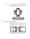
Output Processing
1st or 2nd order high shelf and low shelf filters
10-bands of parametric or 31-band graphic equalizer
Dynamics processing: gate, expander, compressor, limiter, peak limiter
Signal fader gain: +20 to -100 dB
Signal delay: up to 1000 msec
1
2
N
1
2
N
Telco
Processing
Telco
Processing
Telco
Processing
Telco
Processing
Matrix
Processing
SubMix
Submix
Processsing
Output
Processing
Output
Processing
Output
Processing
Input
Processing
Input
Processing
Input
Processing
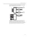
Output Processing
Mute
Output from
Matrix
Dynamics
Processing
Parametric
or Graphic
Equalization
Fader Delay
AEC
Reference
D/A
Converter
Output
Signal
Analog
Gain


