


Design Guide for the Polycom SoundStructure C16, C12, C8, and SR12
3 - 6
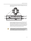
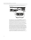
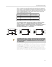
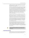
Following the connections in the previous figure, as an example of this linking
order and how the physical channels are numbered, consider the system of
three SoundStructure C16 devices shown in the following figure. In this
example the OBAM output of device A is connected to the OBAM input of
device B and the OBAM output of device B is connected to the OBAM input of
device C. While the individual devices have physical channel inputs ranging
from 1 to 16 and physical outputs ranging from 1 to 16, when linked together,
the physical inputs and outputs of the overall system will both be numbered 1
to 48. These physical channel numbers of all the inputs and outputs will be
important because it will be used to create virtual channels, as will be
discussed in the next section.
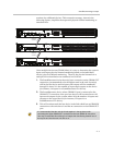
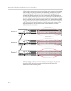
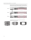
With the linking of devices as shown in the previous figure, the physical
channels will be ordered as expected and shown in that figure and
summarized in the following table.
PIN 2: TXD
PIN 3: RXD
PIN 5: GROUND
PIN 7: CTS
PIN 8: RTS
OBAM IR
RS-232
REMOTE CONTROL 2
REMOTE CONTROL 1
IN OUT
OUTPUTS INPUTS
SoundStructure C16
TM
12V
PIN 2: TXD
PIN 3: RXD
PIN 5: GROUND
PIN 7: CTS
PIN 8: RTS
OBAM IR
RS-232
REMOTE CONTROL 2
REMOTE CONTROL 1
IN OUT
OUTPUTS INPUTS
12V
PIN 2: TXD
PIN 3: RXD
PIN 5: GROUND
PIN 7: CTS
PIN 8: RTS
OBAM IR
RS-232
REMOTE CONTROL 2
REMOTE CONTROL 1
IN OUT
1 2 3 4 5 6 7 8 9 10 11 12 13 14 15 16
OUTPUTS INPUTS
12V
Device A
Device B
Device C
Output Physical Channels 1 - 16
Input Physical Channels 33 - 48
Output Physical Channels 33 - 48