


Design Guide for the Polycom SoundStructure C16, C12, C8, and SR12
6 - 22
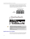
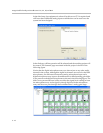
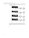
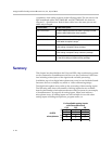
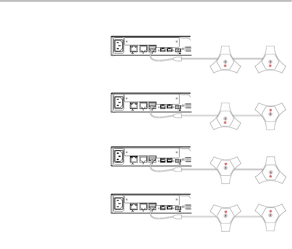
The orientation of the microphone does not affect the sequential numbering as
shown in the following figure.
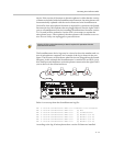
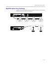
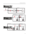
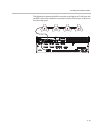
When an HDX system is also connected over the CLink2 interface and the
digital microphones connected directly to the SoundStructure device, the
numbering of the digital microphone arrays will be the same as the previous
figures.
PIN 2: TXD
PIN 3: RXD
PIN 5: GROUND
PIN 7: CTS
PIN 8: RTS
LAN
C-LINK2
OBAM IR
RS-232
IN OUT
12V
PIN 2: TXD
PIN 3: RXD
PIN 5: GROUND
PIN 7: CTS
PIN 8: RTS
LAN
C-LINK2
OBAM IR
RS-232
IN OUT
12V
PIN 2: TXD
PIN 3: RXD
PIN 5: GROUND
PIN 7: CTS
PIN 8: RTS
LAN
C-LINK2
OBAM IR
RS-232
IN OUT
12V
PIN 2: TXD
PIN 3: RXD
PIN 5: GROUND
PIN 7: CTS
PIN 8: RTS
LAN
C-LINK2
OBAM IR
RS-232
IN OUT
12V
POLYCOM POLYCOM
POLYCOM
POLYCOM
POLYCOM
POLYCOM
POLYCOM
POLYCOM
HDX Mic 1 HDX Mic 2
HDX Mic 1 HDX Mic 2
HDX Mic 1
HDX Mic 1
HDX Mic 2
HDX Mic 2