


Design Guide for the Polycom SoundStructure C16, C12, C8, and SR12
9 - 72
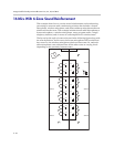
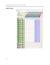
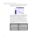
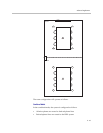
zones. For example, the zone 1 microphones are mapped to zones 2, 3, 4, 5, and
6 with a gain of -9, -6, -6, -9, and -12dB respectively. The zone numbering
matches the room layout description.
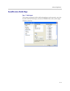
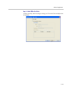
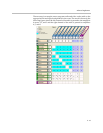
To create a zoned reinforcement system with the reinforcement levels shown
in the table, the matrix crosspoints for the zones must be adjusted to match the
designed reinforcement matrix. The first step is to create the zone groups and
then map the zone groups to the amplifier outputs with the desired cross-
points and sound reinforcement version of the input processing.
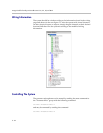
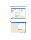
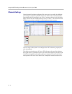
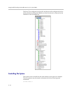
To create the different zones, select the Edit Groups... button and follow the
instructions in the section Creating Virtual Channel Groups in Chapter 5. The
result should be six zones of microphones that include the microphones
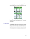
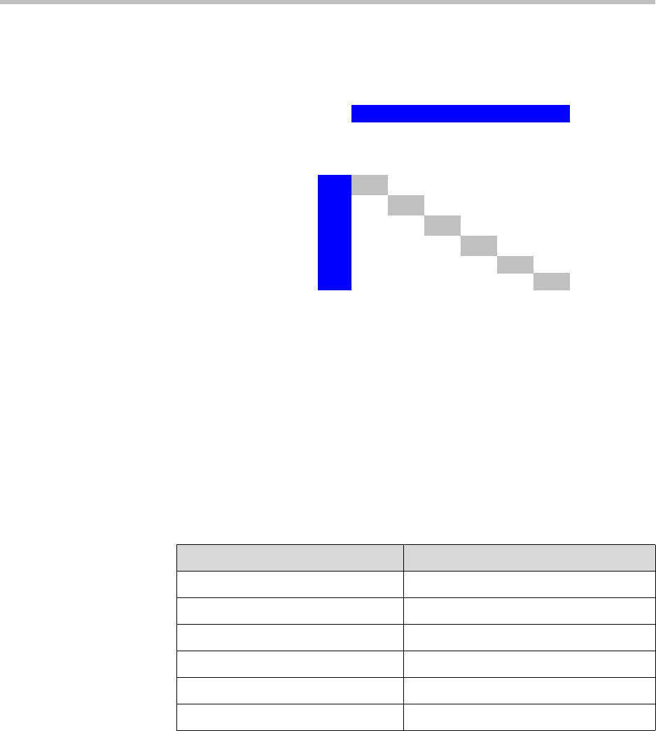
shown in the drawing of the room. Once the zones have been created into vir-
tual channel groups, the groups may be collapsed so that the matrix operates
at the group level - hiding the detail of the underlying microphones as shown
in the following figure.
In this example Zone 1 includes the microphones shown in the following table.
123456
-6 -6 -6 -6 -6
-6 -6 -6 -6 -6 -6
1 -9 -6 -6 -9 -12
2 -9 -9 -9 -12 -9
3 -6 -9 -12 -9 -6
4 -6 -9 -12 -12 -6
5 -9 -12 -9 -12 -12
6 -12-9-6-6-12
Amplifier
Zone
Lectern
Wireless
Zone Microphones
Zone 1 1 and 2
Zone 2 3, 4, 5, and 6
Zone 3 7 and 8
Zone 4 9 and 10
Zone 5 11, 12, 13, and 14
Zone 6 15 and 16