


Design Guide for the Polycom SoundStructure C16, C12, C8, and SR12
3 - 18
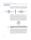
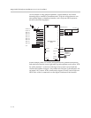
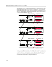
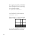
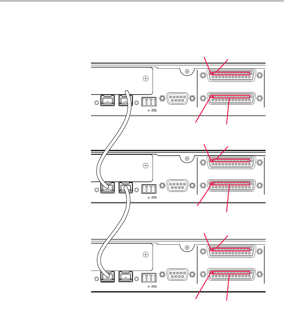
When multiple devices are OBAM linked as shown in the next figure, the logic
inputs and outputs on the first device will be numbered 1 - 22 and the logic
inputs and outputs on the second device (device B) will be numbered 23 - 44,
and so on. The analog gain inputs will be numbered 1 and 2 on the first device,
3 and 4 on the second device, and so on.
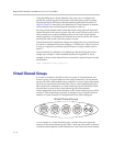
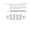
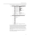
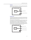
Due to the one large system design philosophy, logic input pins on any device
can be used to control features on any SoundStructure device - not just provide
control on the device the logic inputs are on. Similarly logic outputs can be
used to provide status on signals on any SoundStructure device - not just
status on a physical channel on that particular device.
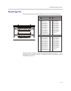
PIN 2: TXD
PIN 3: RXD
PIN 5: GROUND
PIN 7: CTS
PIN 8: RTS
OBAM IR
RS-232
REMOTE CONTROL 2
IN OUT
12V
REMOTE CONTROL 1
PIN 2: TXD
PIN 3: RXD
PIN 5: GROUND
PIN 7: CTS
PIN 8: RTS
OBAM IR
RS-232
REMOTE CONTROL 2
IN OUT
12V
REMOTE CONTROL 1
PIN 2: TXD
PIN 3: RXD
PIN 5: GROUND
PIN 7: CTS
PIN 8: RTS
OBAM IR
RS-232
REMOTE CONTROL 2
IN OUT
12V
REMOTE CONTROL 1
Logic Outputs 23 - 33
Logic Outputs 23 - 33
Logic Outputs 34 - 44
Logic Outputs 1 - 11Analog Gain Input 1
Logic Outputs 12 - 22
Logic Outputs 34 - 44
Analog Gain Input 2
Analog Gain Input 3
Analog Gain Input 4
Analog Gain Input 5
Analog Gain Input 6