


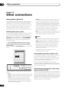
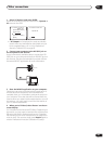
Other connections
10
86
En
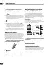
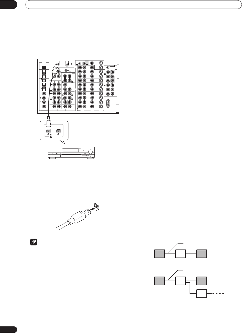
• Use an i.LINK cable to connect one of the i.LINK
connectors on this receiver to an i.LINK connector on
your i.LINK component.
• The arrow on the cable connector body should be
face down for correct alignment with the connector
on the player. When properly connected, the i.LINK
plug will snap into the connector. If not connected
properly the receiver will not be able to recognize any
connected components.
Note
• You can connect several components together using
i.LINK. See Creating an i.LINK network below.
About i.LINK
i.LINK is a trademark name for IEEE1394, a high-speed
interface for digital audio, video and other data found on
personal computers, digital camcorders, and other kinds
of audio and audio/visual equipment. A single i.LINK
connector can both send and receive data at the same
time, so only one cable is required to connect compo-
nents for two-way communication.
“i.LINK” and the “i.LINK” logo are trademarks of Sony
Corporation.
About PQLS rate control
Pioneer's PQLS (Precision Quartz Lock System)
technology provides high-precision digital audio from
DVD-A, SACD and audio CD sources when you use the
i.LINK interface. A precision quartz controller in this
receiver eliminates distortion caused by timing errors
(jitter), giving you the best possible digital-to-analog
conversion from the digital source.
To take advantage of PQLS, you must have a player
compatible with rate-control, and it must be switched on
and connected to this receiver through the i.LINK
network.
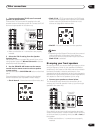
Creating an i.LINK network
Using i.LINK it is possible to chain up to 17 components
together so that the digital audio and control signals
from each component is available to other components
in the network. With the addition of an i.LINK repeater,
it’s possible to connect up to 63 components.
i.LINK connectors come in 4-pin and 6-pin configura-
tions. This player uses the 4-pin connection, but the two
types can be mixed on a network.
This receiver is compatible with i.LINK Audio (A&M
protocol) components, such as DVD players. Note that
when connected to i.LINK MPEG-II TS equipment (such
as a digital satellite tuner), i.LINK DV equipment (such as
a DVD recorder or DV camcorder), or an i.LINK-equipped
personal computer, audio and video signals are not
transmitted, and connecting to these devices sometimes
causes network interruptions. Check the operating
instructions supplied with your other i.LINK components
for compatibility information.
This receiver is DTCP (Digital Transmission Content
Protection) compliant, so you can play DVD-A, DVD-
Video, and SACD i.LINK audio.
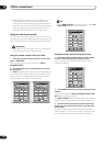
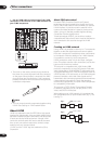
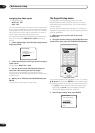
When setting up an i.LINK network, it’s important that
the components form an open ended chain (fig. 1), or a
tree (fig. 2).
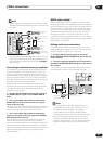
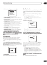
PLAY
PLAY
AUDIO POWER
AMP
IN
PRE OUT
AUDIO
PHONO
FRONT SUB W CENTER
SUR-
ROUND
BACK
SUR-
ROUND
SUB W.
CENTER
SUR-
ROUND
CD-R/
TAPE1/
MD
TAPE 2
MONITOR
CD
IN
IN
IN
OUT
IN
OUT
VIDEOAUDIO S2 VIDEO
USB AUDIO
S400 (AUDIO)
OUT 2
OUT 1
(CD-R/
TAPE1/
MD)
(DVR/
VCR1)
(SAT)
IN
(CD)
(TV/
DVD)
(DVD/
LD)
(DVD/
LD)
IN
DVR/
VCR1
OUT
DVD/
LD
IN
(DVD/
LD)
IN
Y
P
B
PR
PB
PR
2RF
IN
IN
IN
Y
P
B
PR
Y
P
B
PR
Y
TV/
DVD
IN
SAT
IN
IN
IN
MULTI-
ROOM &
SOURCE
MULTI ROOM &
SOURCE
IN
IN
OUT
OUT
OUT
12V TRIGGER
IN
IN
IN
VCR2
OUT
IN
VCR3
OUT
IN
1 IN
REC
REC
OUT
DIGITAL
MONITOR
OUT 1
MONITOR
OUT 2
MONITOR
OUT
COMPONENT VIDEO
ASSIGNABLE MULTI CH INPUT
RS-232C
REMOTE IN
2 IN
3 IN
4
IN
5
R L
R L
RL
RL
(Single)
1
(Single)
2
(Single)
RL
R
L
R L
R L
R L
IN
6
ASSIGNABLE
CONTROL
IN
3
1
2
(AUDIO)
S400
i.LINK-equipped component
fig. 1
fig. 2
i.LINK cable
i.LINK cable