


Other connections
10
85
En
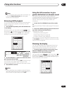
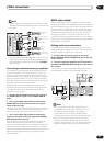
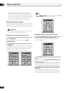
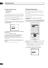
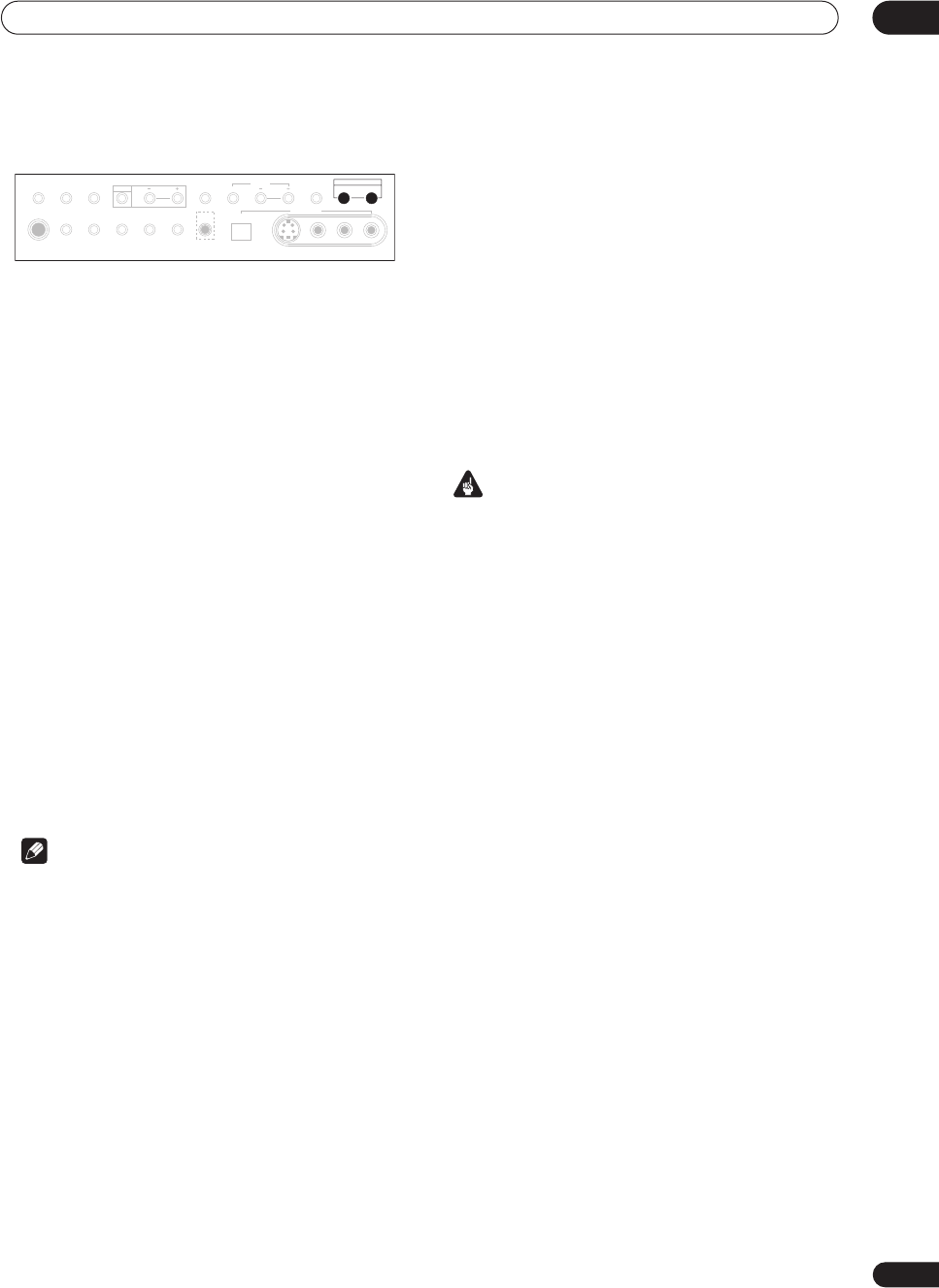
Using the front panel multi-room controls
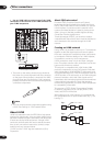
1 Press the MULTI ROOM & SOURCE ON/OFF
button on the front panel.
The MULTI ROOM indicator lights on the front panel to
indicate the multi-room control has been switched on.
2 Press CONTROL.
Make sure that any operations for the sub room are done
while MULTI ROOM shows in the display. If MULTI
ROOM is not showing, the front panel controls affect the
main room only.
3 Use the INPUT SELECTOR dial to select the source.
Select between DVD/LD, TV/DVD, SAT, DVR/VCR 1, CD,
CD-R/TAPE 1 or TUNER (in that order).
If you select TUNER, you can use the front panel TUNER
controls to select a preset station (see Listening to
memorized station presets on page 56 if you’re unsure
how to do this).
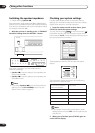
4 Use the MASTER VOLUME dial to adjust the
volume.
This is only possible if you selected the VARIABLE
volume control in Multi-Room Setting on page 95.
5 When you’re finished, press CONTROL again to
return to the main room controls.
You can also press the MULTI ROOM & SOURCE ON/
OFF button on the front panel to switch off all output to
the sub room.
Note
• Multi-room can’t be used when you’re setting up the
system (from the on-screen System Setup menu).
• If you’re using a Pioneer amplifier in the sub room,
you may want to cover the remote sensor so that this
remote control doesn’t accidently control the sub
room amplifier.
• You won’t be able to switch the main room off
completely unless you’ve switched off the multi-room
control first.
• When someone is controlling the system from the
main room, you won’t be able to operate the sub
room controls.
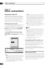
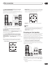
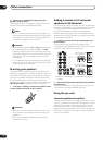
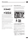
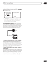
Using the i.LINK interface
If you have a component with an i.LINK connector, you
can connect it to this receiver using an i.LINK cable.
Since the i.LINK interface does not transmit video
signals, the video signal of i.LINK-connected compo-
nents must be connected with other cables (see
Connecting your equipment on page 14 for more on
making video connections). If you’ve already hooked up
the video signal from the component, assign the i.LINK
input to the input function to which you’ve connected the
video signals (see Assigning the i.LINK inputs on
page 91).
The two i.LINK connectors on the rear of your receiver are
4-pin connectors. Use a 4-pin, S400 i.LINK cable to
connect i.LINK-equipped components.
Important
• Please use 4-pin, S400 cables less than 3.5 meters
long. Although longer ones are available, they may
not work reliably.
• If your i.LINK connector comes into contact with
metallic parts of the receiver other than the i.LINK
terminal, an electrical short may occur. Some cables
have metal parts that may touch the unit when
connected. Please take care to use a suitable i.LINK
cable only.
• There may be cases where the PQLS/rate control
function and/or the i.LINK audio does not work prop-
erly even when connected to i.LINK Audio-compat-
ible equipment.
• During playback through an i.LINK connection, do
not disconnect i.LINK cables or switch off any
components connected using i.LINK.
• Copy-protected 96kHz DVD-Video discs can be heard
through the i.LINK connection, but they will be down-
sampled to 48kHz.
PHONES
SP SYSTEM
A/B
SIGNAL
SELECT
VIDEO
SELECT
TAPE2
MONITOR
STREAM
DIRECT
SETUP
MIC
SB CH
MODE
DIGITAL IN
S-VIDEO VIDEO
VIDEO INPUT
AUDIOLR
MIDNIGHT
TONE OPTION DIGITAL NR CLASS STATION
MULTI ROOM & SOURCE
CONTROL ON/OFF
TUNER
ACOUSTIC
CAL.