


Connecting your equipment
02
15
En
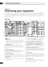
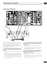
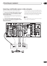
8 Pre-amplifier output/power amplifier input
When using this receiver as an integrated amplifier, leave
the pre-amp outputs connected to the power amp inputs
with the supplied U-shaped connectors. Removing these
connectors allows you to use this unit as a pre-amplifier
or power amplifier only, or to integrate another amplifier
into your setup for more inputs. See Using the pre-outs on
page 82 for connection details.
9 Multichannel pre-amplifier outputs
Multichannel pre-amp outputs that you can use to
connect separate amplifiers for center, surround,
surround back and subwoofer channels. See Using the
pre-outs on page 82 for connection details.
10 Control input/output
Mini jack terminals for connection to other Pioneer
components to enable you to control all your equipment
from a single IR remote sensor. See Operating other
Pioneer components with this unit’s sensor on page 74
for connection details.
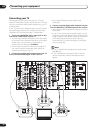
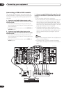
11 Monitor video outputs
Three video outputs consisting of a standard composite
video output and two S-video outputs, for connection to
monitors and TVs. See Connecting your TV on page 16 for
connection details.
12 Multi-room and source outputs
Outputs for connection to a second amplifier in a
separate room. See Multi-room setup on page 83.
13 Audio/video source inputs
Each of the seven source input functions has stereo
analog audio jacks, a composite video jack and an S-
video jack for basic connections. On top of these, you can
assign digital audio and component video jacks to input
functions as necessary. As well as audio/video inputs,
the three input functions DVR/VCR 1, VCR 2 and VCR 3
also have audio/video outputs for recording. See
Connecting a VCR or DVD recorder on page 20 for
connection details.
14 Remote input (multi-room and source)
The remote input allows you to connect an external
remote control sensor, for use in a multi-room setup, for
example. See Multi-room setup on page 83 for
connection details.
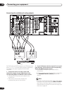
15 Component video inputs/output
The three component video inputs are freely assignable
to any of the audio/video input functions. The component
video output is for connection to a monitor or TV. See
Using the component video jacks on page 22 for
connection details.
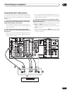
16 RS-232C connector
This port is provided for connecting a personal computer
for graphical output when using Advanced MCACC.
17 Antenna terminals
Connections for AM and FM radio antennas. See
Connecting antennas on page 28 for connection details.
18 12V trigger jacks
These terminals output DC 12V according to the input
functions (total 100 mA max.). See Switching
components on and off using the 12 volt trigger on
page 74 for connection details.
19 Speaker terminals
These are the main speaker terminals for front, center,
surround and surround back speakers. See Installing
your speaker system on page 26 for connection details.
20 AC power outlet
This 120V AC power outlet can be used to power another
component in your setup (up to 100 W). Power to this
outlet is switched off when the receiver is in standby.
21 AC power inlet
Connect the supplied power cord here.
22 B speaker terminals
Stereo B speaker terminals that you can use to connect
a second pair of speakers for use in another room, for
example. See Using speaker system B on page 80 for
connection details.
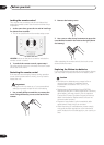
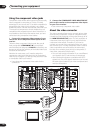
When making cable connections
Be careful not to arrange cables in a manner that bends
the cables over the top of this unit. If the cables are laid
on top of the unit, the magnetic field produced by the
transformers in this unit may cause a humming noise to
come from the speakers.
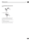
• When connecting optical cables, be careful when
inserting the plug not to damage the shutter
protecting the optical socket.
• When storing optical cable, coil loosely. The cable
may be damaged if bent around sharp corners.