


8 205486 REV F Operations Manual, HPA2, Compact Outdoor SSPA
Figure 11-6: Connect To window ............................................................................ 110
Figure 11-7: COM Properties window ..................................................................... 111
Figure 11-8: ASCII Setup window ........................................................................... 111
Figure 11-9: Example of Terminal Mode session .................................................... 112
Figure A-1: Quick Start Cable Schematic ................................................................ 113
Figure B-1: Mixed System using New and Original Compact Outdoor SSPAs ....... 115
Figure B-2: Redundant System using RCP2-1100 Controller ................................. 116
Tables
Table 2-1: AC Line Input Connector .......................................................................... 11
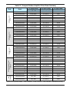
Table 2-2: Compact Outdoor Amplifier Prime Power Summary ................................ 12
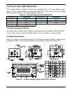
Table 2-3: DC Input Connector, MS3102E-20-29P ................................................... 13
Table 2-4: Link Port (J5) Pin-Outs ............................................................................. 14
Table 2-5: Switch Port (J6) Pin-Outs ......................................................................... 15
Table 2-6: +15 VDC Output Port (J8) Pin-Outs ......................................................... 15
Table 2-7: Compact Outdoor SSPA Weights ............................................................ 20
Table 2-8: Compact Outdoor SSPA Mounting Kit ..................................................... 21
Table 3-1: Monitor & Control Connector, J4 ............................................................. 26
Table 7-1: Returning Amp 2 to Stand-by Mode After Fault on Thread 1 or 3 ............ 65
Table 9-1: ZBUC Frequency Specifications .............................................................. 82
Table 9-2: ZBUC RF output phase noise specification.............................................. 83
Table 9-3: Common Coaxial Cable Characteristics .................................................. 85
Table 10-1: Command Byte Values .......................................................................... 88
Table 10-2: Data Tag Byte Values ............................................................................ 89
Table 10-3: Error Status Byte Values ........................................................................ 90
Table 10-4: Request Frame Structure ....................................................................... 92
Table 10-5: Response Frame Structure .................................................................... 92
Table 10-6: System Settings Data Values ................................................................. 93
Table 10-7: System Condition Addressing ................................................................ 94
Table 10-8: ADC (Analog-Digital Converter) Addressing .......................................... 95
Table 10-9: System Threshold Data Values .............................................................. 95
Table 10-10: Example 1 Host PC Request String ..................................................... 96
Table 10-11: Example 1 SSPA Response String ...................................................... 97
Table 10-12: Example 2 PC Request String ............................................................. 98
Table 10-13: Example 2 SSPA Response String ...................................................... 98
Table 10-14: Example 3 PC Request String ........................................................... 100
Table 10-15: SSPA Fault Status bit by bit description ............................................. 100
Table 10-16: Example 3 SSPA Response String ....................................................
101
Table C-1: Baud Rate and Protocol Reverting Options ........................................... 117
Table C-2: Unique Network Address Hardware Select ........................................... 117
Table D-1: Suggested Cable Wiring for ND Satcom SkyWAN modems ................. 119
Table D-2: Packet Structure .................................................................................... 120
Table D-3: Response Structure ............................................................................... 120
Table D-4: Power Class Values .............................................................................. 121