


48 205486 REV F Operations Manual, HPA2, Compact Outdoor SSPA
7.1.1 Hardware Setup
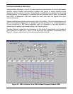
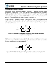
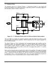
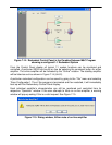
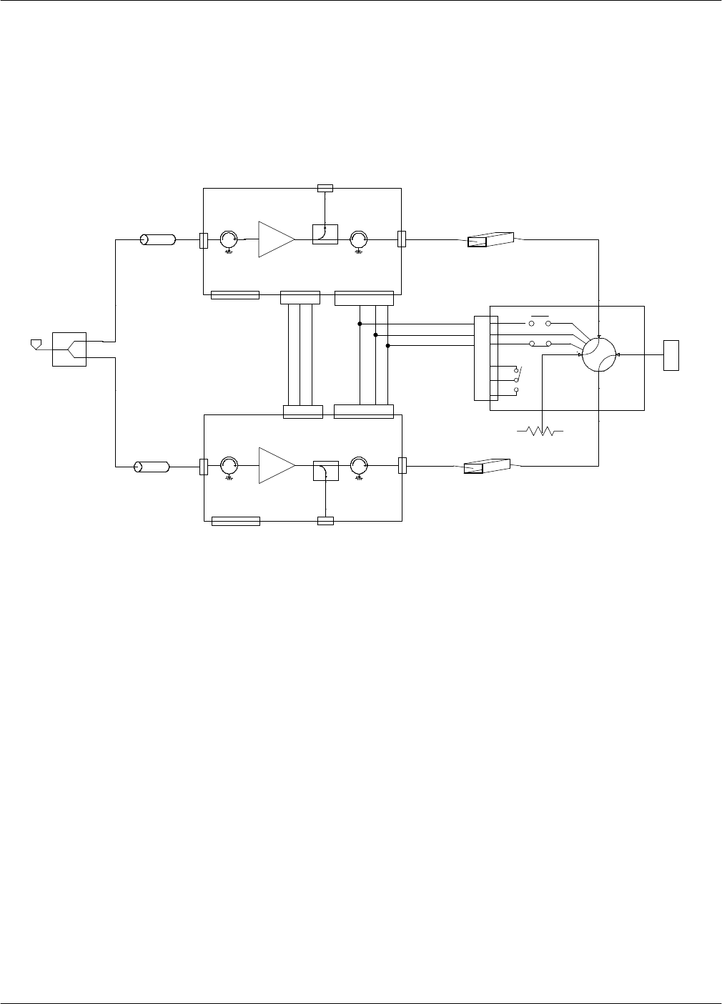
The hardware setup for a Compact Outdoor 1:1 Redundant System is very simple and
involves the addition of (2) cables along with a redundancy switch. A schematic diagram of
the redundancy setup is shown in Figure 7-6.
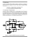
The Link Cable is a simple (3) conductor crossover cable that allows the system to pass
command and control between amplifiers. With the redundancy kit, this cable is supplied in a
26 inch (660mm) length.
The Switch Cable is a “Tee” configuration and connects between each amplifier and the
redundancy switch. The Redundancy Switch is a –28 VDC type. Therefore the controller in
each Compact Outdoor Amplifier is capable of supplying +28 VDC to the common voltage
input. Either controller may then provide a (sink) return to engage either position 1 or position
2 of the redundancy switch.
Care must be observed when connecting this cable to the amplifiers. The cable end labeled
“A1” must be connected to the amplifier whose output is connected to Port 3 of the waveguide
switch. Likewise the cable end labeled “A2” must be connected to the amplifier whose output
is connected to Port 1 of the waveguide switch. This is for proper identification purposes of
the Redundancy Control Firmware used by each Compact Outdoor Amplifier.
Figure 7-6: 1:1 Redundant System with Link Cable and Switch Cable installed
&
CONTROL
MONITOR
J4
J3
OUTPUT SAMPLE
J3
OUTPUT SAMPLE
A
B
F
BF
LINK
LINK
J5
J5
A
B
C
D
E
F
1
2
4
3
SSPA 1
SSPA 2
EC
C
EF
RF OUTPUT
SWITCH
&
CONTROL
MONITOR
J4
LINK
CABLE
SWITCH CABLE
A
F
J6
SWITCH
A2 (J6)
A1 (J6)
J6
SWITCH