


Operations Manual, HPA2, Compact Outdoor SSPA 205486 REV F 67
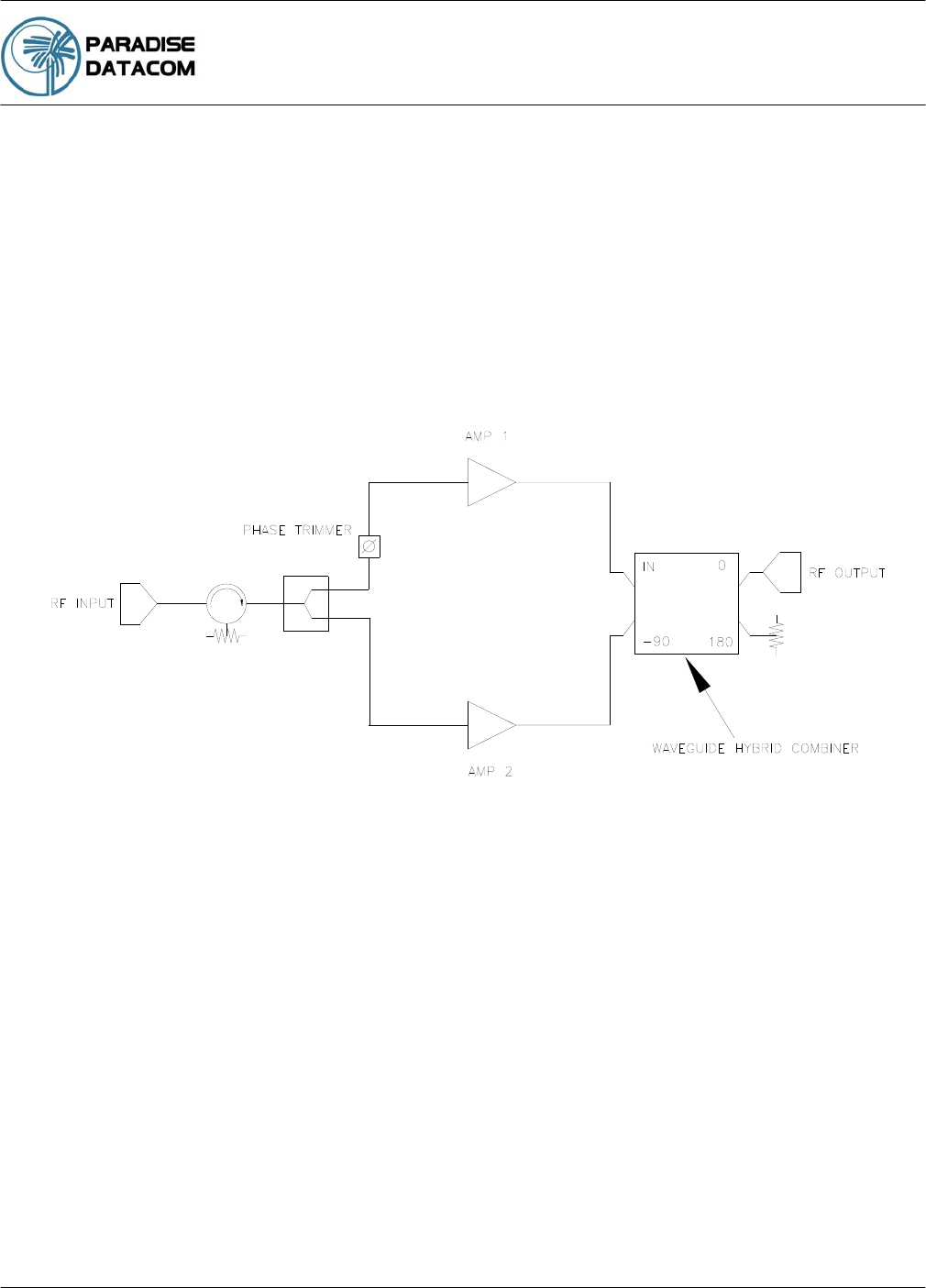
8.0 Phase Combining Overview
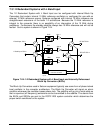
Phase combining amplifiers has long been a popular means of increasing the output power of
an amplifier system. Under high power microwave conditions it is common to utilize some
form of waveguide hybrid coupler to combine the output power of two amplifiers. This coupler
is generally a waveguide tee such as a four port magic tee. On the input side, common
coaxial power splitters can be utilized to divide the power due to the lower power levels at the
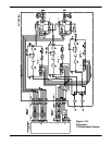
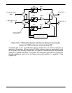
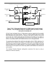
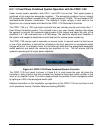
input of the system. Figure 8-1 shows a typical block diagram of a phase combined amplifier
pair. As long as the electrical delay, phase and amplitude of the two paths are kept within
close tolerance of each other, the output power of the system will be twice the output power
(+3dB) of a single amplifier.
The main drawback of this approach is that in the event of an amplifier failure, the total output
power decreases by 6 dB, or a factor of 4. This does not offer the system much in the way of
redundant capability with such a large decrease in output power capability. The power
decrease is due to the fact that with only one amplifier active, the output combiner acts as a
power divider. The output power from the remaining amplifier is divided between the output of
the system and the terminated port of the hybrid combiner. Thus only one half of the power
from one amplifier reaches the output port which is 6 dB less than the combined output power
from both amplifiers. A high power system requiring a degree of redundancy needs some
means of bypassing the combiner in the event of an amplifier failure. This would allow the full
output power capacity of the remaining amplifier to reach the output. In this case the total RF
output power would only decrease by 3 dB from the phase combined output power. A 3 dB
reduction in output power is generally more tolerable to a system’s link budget thereby giving
the system a degree of redundancy.
Figure 8-1: Phase Combined Amplifier System
Section 8: Fixed Phase Combined
Redundant Systems