


78 205486 REV F Operations Manual, HPA2, Compact Outdoor SSPA
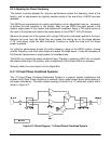
The Signal Box also contains two phase shifters. These phase shifters are in cascade with
the RF input to HPA 1 and HPA 3. These allow the system to achieve optimum power
combining and are factory set for optimum combining across the full bandwidth of the
amplifier. They should not normally require adjustment in the field unless and amplifier has
been replaced.
8.5 1:2 Fixed Phase Combined System Operation with FPRC-1200
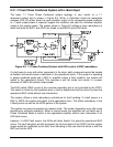
Under normal system operation, HPA 1 and HPA 3 are on-line. Their output power is
combined at the magic-tee waveguide combiner. The waveguide combiner has an integral RF
sampler that provides a sample of the RF output sample at -40 dBc. This port feeds an RF
attenuator / diode detector combination. The detector’s output voltage is sent back to the
Signal box via a coaxial cable and fed to the FPRC-1200 Redundant Controller.
The 1:2 Fixed Phase Combined System is controlled by an FPRC-1200 1:2 external
Redundancy Controller. Detailed information on the installation and operation of the FPRC-
1200 can be found in the unit’s operations manual, Paradise Datacom drawing #201138.
The FPRC-1200 can be used in automatic or manual mode. In manual mode if a fault occurs
in one of the amplifiers, a fault will be indicated on the front panel but no waveguide switch
change will occur. In automatic mode the controller will determine the appropriate waveguide
switch positions and switch the remaining two amplifiers on line. This will ensure that the
system is operating at full output power capability.
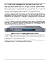
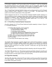
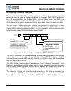
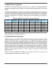
The FPRC-1200 front panel is shown in Figure 8-9. In most cases the user will place the
controller in Auto mode so that the controller can determine the proper switch position in the
event of an amplifier failure. The mimic display shows the position of each waveguide switch
by lighting an LED in the waveguide switch path.
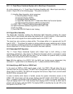
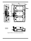
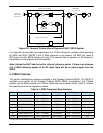
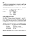
In normal operation, HPA 2 should be selected as the standby amplifier. HPA 2 is the middle
amplifier on the amplifier frame. This allows HPA 1 and HPA 3 to be combined by the
waveguide combiner. If HPA 1 or HPA 3 were to ever fail, HPA 2 can be switched in place of
either HPA 1 or HPA 3 and the system will still maintain full output power capability over the
full operating bandwidth of the amplifier. Figure 8-10 shows the FPRC-1200 with HPA 2
selected as the standby amplifier.
Figure 8-9: FPRC-1200 1:2 Phase Combined Redundant Controller
Figure 8-10:
HPA 1 & HPA 3 on line
with HPA 2 on standby