


16 205486 REV F Operations Manual, HPA2, Compact Outdoor SSPA
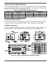
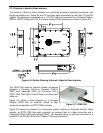
2.5.8 AC Input (J7)
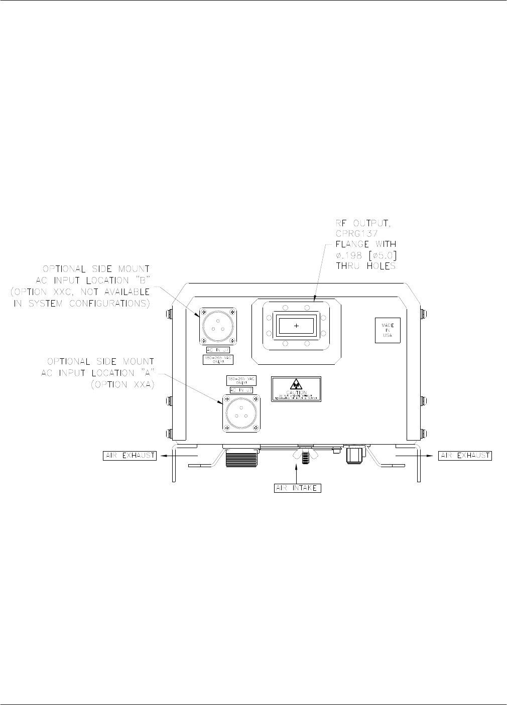
The AC Input connector, J7, is located on the bottom side of the Compact Outdoor Amplifier
package. There are also two alternate placements for this connector on the RF Output end of
the amplifier as shown in Figure 2-4. This connector is a 3-pin circular connector, MS3102E20
-3P. The mating connector (MS3106E20-3S) is shipped with the unit. The pin out for this con-
nector is given in Table 2-1.
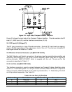
2.5.9 RF Output (J2)
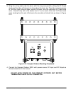
The RF Output is brought out through waveguide in the Compact Outdoor Amplifier. Figure
2-4 shows the output of a C-Band Compact Outdoor Amplifier. The Ku-Band amplifiers have a
WR75 grooved flange, while the C-Band and X-Band amplifiers have CPR style grooved
flanges (CPRG-137 for C-Band; CPRG-112 for X-Band). Ka-Band amplifiers utilize a WR28
grooved flange. S-Band units are fitted with Type N (F) connectors at the RF Output.
An isolator is provided at the output flange with a termination capable of handling full reflected
output power.
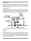
2.6 Airflow
The air intake and exhaust are both located on the bottom side of the amplifier. The intake is
brought through three fans while the exhaust is along the two rows of heat sink fins as seen in
Figure 2-4. A minimum clearance of 6 inches (152 mm) should be maintained between
the fans and any surface during operation. This will ensure that there is no forced
re-circulation of airflow from exhaust to intake. The Compact Outdoor SSPA should NEVER
be mounted with the fans facing up.
Figure 2-4: RF Output Side of C Band Compact Outdoor SSPA
RF OUT
J2