


Operations Manual, HPA2, Compact Outdoor SSPA 205486 REV F 15
2.5.4 RF Output Sample Port (J3) [N-type (F)]
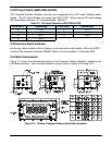
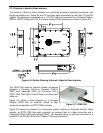
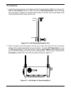
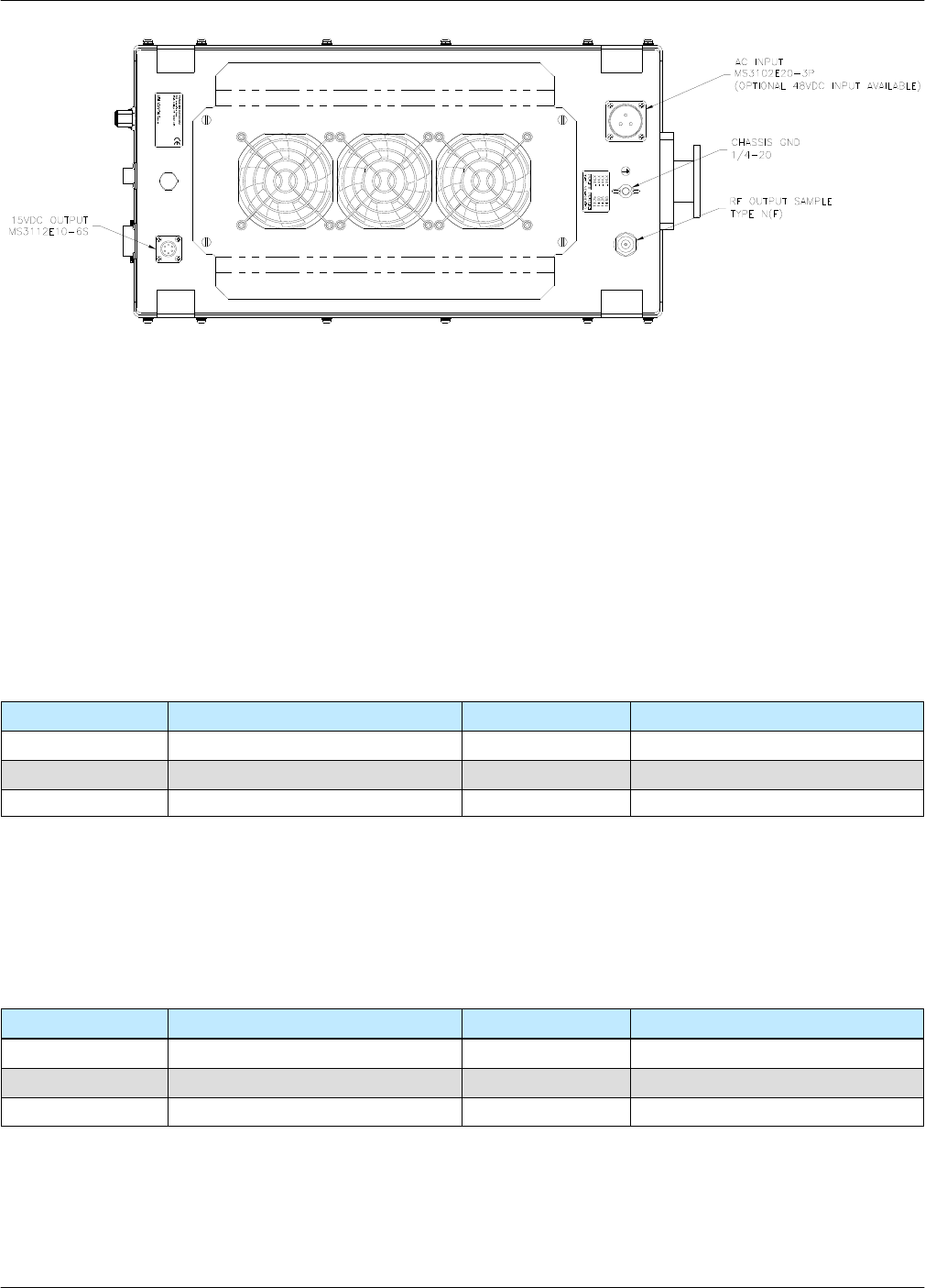
The RF Output Sample port, J3, is located on the bottom of the amplifier as shown in Figure 2
-3. This connector provides a -40 dBc sample of the amplifier’s output signal. It is a N-type
female connector.
2.5.5 Switch Port (J6) [MS3112E10-6S]
When used in a 1:1 redundant system, the waveguide switch must be connected to the switch
port of each amplifier (MS3112E10-6S). See Table 2-5.
2.5.6 15 VDC Output Port (J8) [MS3112E10-6S]
The 15 VDC Output, J8, is located on the bottom side of the amplifier as shown in Figure 2-3.
This provides +15 VDC and up to 1 Amp current to any external equipment. It is a 6-pin
MS-type connector. See Table 2-6.
2.5.7 Chassis Ground Terminal
A Chassis ground terminal is provided on the bottom side of the amplifier. A ¼ - 20 threaded
terminal is provided for equipment grounding.
Figure 2-3: Bottom View, Compact Outdoor Amplifier
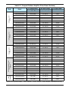
Table 2-5 Switch Port (J6) Pin-Outs
Pin # on J6 Connection Pin # on J6 Connection
A N/C D N/C
B N/C E POS 2
C +28 VDC F POS 1
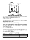
Table 2-6: +15 VDC Output Port (J8) Pin-Outs
Pin # on J8 Connection Pin # on J8 Connection
A EXTERNAL FAULT IN D GND
B FAULT PULLUP E +15V EXTERNAL
C +15V LNA F GND
AUX POWER
J8
MODEL: XXXX XXXXXXXX
P/N: LXXX XXX-X
S/N: XXXX
SAMPLE
J3
J7
AC IN