


Operations Manual, HPA2, Compact Outdoor SSPA 205486 REV F 69
power combining. To the operator, the system appears as a single amplifier. The operator
can choose between using the system as a phase combined system or a traditional
redundant system.
8.1 1:1 Fixed Phase Combined System Components
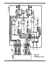
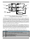
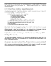
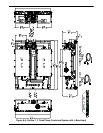
An outline drawing of a 1:1 Fixed Phase Combined Amplifier assembly is shown in Figure 8-3
on the following page. The system consists of:
(1) Amplifier Base Assembly, which comprises:
(1) Mounting Base (Frame or Plate)
(2) Compact Outdoor SSPAs
(1) Waveguide Switch Assembly
(1) Signal Box Assembly
(2) Cable Assemblies between SSPAs and Signal Box
(1) FPRC-1100 1:1 Phase Combined Redundant Controller
(2) Cable Assemblies between Signal Box and FPRC-1100
(2) AC line cables
(1) Quick Start RS-232 Cable for test / debug
The Amplifier Base Assembly is typically shipped intact. Verify that the hardware is securely
tightened for each Compact Outdoor amplifier and make sure to observe the amplifier’s
position indicator. If facing the RF Output end of the amplifiers, HPA 1 should be on the left
hand side and HPA 2 should be on the right hand side as shown in Figure 8-3.
Verify that the connections of the Waveguide Switch Assembly mate with the proper SSPA.
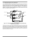
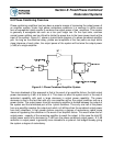
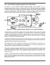
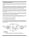
8.1.1 Signal Box Assembly
The Signal Box Assembly contains the RF input isolator and splitter that routes the RF to
each amplifier. It also routes the monitor and control signals from each amplifier back to the
FPRC-1100 system controller.
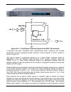
The signal box also contains a phase shifter. This phase shifter is in cascade with the RF
input to HPA 1. This allows the system to achieve optimum power combining and is factory
set for optimum combining across the full bandwidth of the amplifier. It should not normally
require adjustment in the field unless and amplifier has been replaced.