


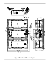
64 205486 REV F Operations Manual, HPA2, Compact Outdoor SSPA
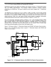
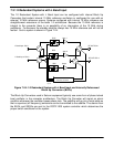
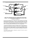
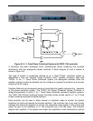
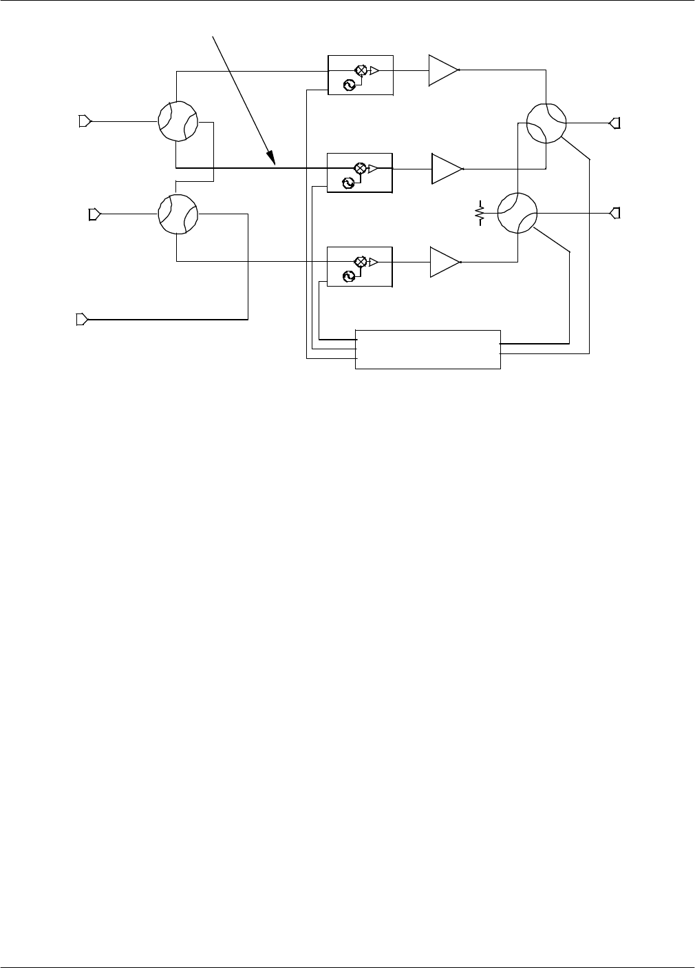
At first it may be thought that a 10 MHz signal could be injected into the normally
terminated port of the input switches. While in a normal operating state with all three
BUCs operational this would work fine. However in the event of a failure of one of the
on-line units, the 10 MHz would also be interrupted to the standby unit, as shown in
Figure 7-26. Due to the quick determination of a unit fault, the controller will interpret a
fault on the standby amplifier and reliable switchover can not be guaranteed.
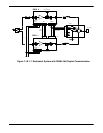
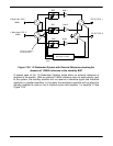
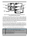
To overcome the problems that result from interruption of the 10 MHz reference, it is
imperative that the reference be injected in the system after the waveguide switches.
One technique could be to install a multiplexer on the input of each amplifier that would
allow the injection of the 10MHz reference. In this case a separate 10 MHz line would
have to be run to the system and a three way splitter could distribute the reference to
each amplifier.
The standard Paradise Datacom configuration overcomes this issue by using a
Reference Combiner assembly.
RF OUT-POL 2
RF OUT-POL 1
Amp 1
Amp 2
Amp 3
RCP2-1200
Redundant Controller
BUC
L Band Input- POL 1
L Band Input- POL 2
BUC
BUC
Alarm
Inputs
Switch Drive
10MHz
10MHz
10 MHz, Standby
During Switch-Over, 10MHz is interrupted to Standby BUC
Figure 7-26: 1:2 Redundant System with (3) 10MHz inputs through the input
switches. This arrangement allows for unreliable switch-over due to 10 MHz
interruption to standby unit