


Operations Manual, HPA2, Compact Outdoor SSPA 205486 REV F 45
7.0 Redundant System Concepts
The Compact Outdoor Amplifier is capable of operating in a variety of redundant system
configurations. These include 1:1 and 1:2 as well as 1:1 with L-Band Block Up Converters.
The Compact Outdoor Amplifier has a built-in 1:1 redundancy controller, allowing it to be used
in 1:1 redundant systems without a separate external controller. When used in a 1:2
redundant system a separate controller, RCP2-1200, is required. The three most common
forms of 1:1 redundant system are shown in Figures 7-1 through 7-3.
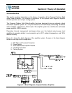
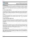
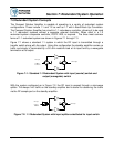
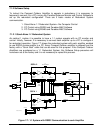
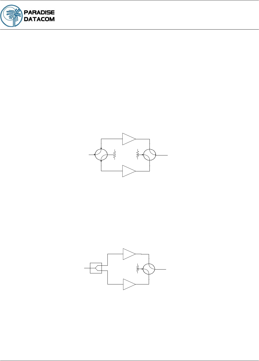
Figure 7-1 shows a standard 1:1 system in which the RF input is transmitted through a
transfer switch along with the output. Using this configuration the standby amplifier carries no
traffic and simply is terminated by a 50 ohm resistive load at its input and by a waveguide
termination at its output.
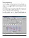
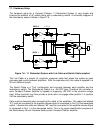
With the system configured as in Figure 7-2, the RF input is passed through a microwave
splitter. This keeps ‘live’ traffic on the standby amplifier and is useful for observing the traffic
via the RF sample port on the standby amplifier.
C Band
or
Ku Band
RF Input
RF Output
Figure 7-1: Standard 1:1 Redundant System with input (coaxial) switch and
output (waveguide) switch
C Band
or
Ku Band
RF Input
RF Output
Figure 7-2: 1:1 Redundant System with input splitter substituted for input switch
Section 7: Redundant System Operation